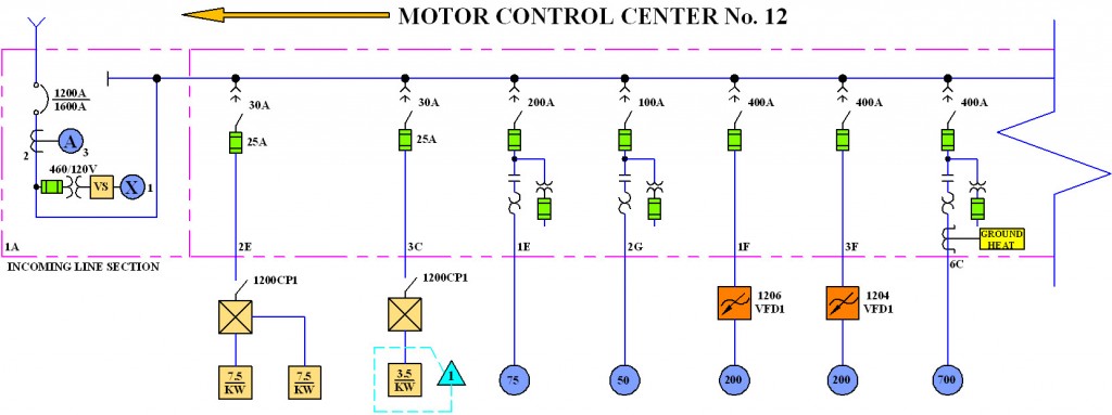
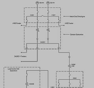
Instead you can click its icon and then hit on the location where you want to place it. In this electrical circuit is graphically represented in a simplified manner.
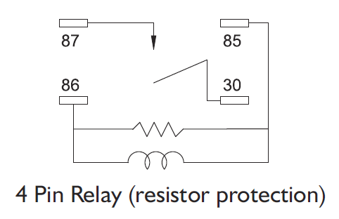
Semiconductor Symbols For Electrical Schematic Diagrams
Types of electrical diagrams. Electronic schematic drawing symbology. It is a functional drawing which shows and describes the main operating principles of the equipment or. Unlike a schematic its. Open edraw electrical diagram maker and this large collection of symbols are found in the engineering category in the available templates list. It does not show the actual locations of the components. Usually drawn like a ladder hence the name ladder diagram.
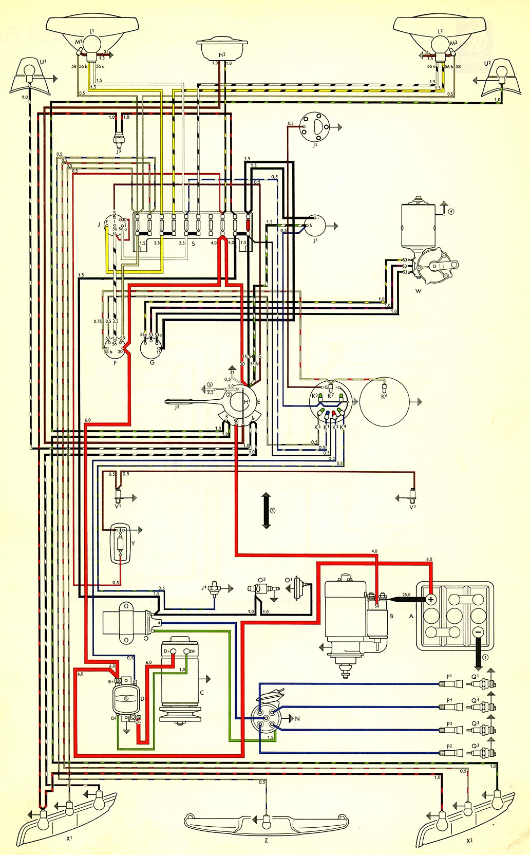
After you start edraw click the icon of basic electrical symbols to open the stencil that includes all shapes for making circuit diagrams. What are the different types of electrical diagrams. Types of drawings block diagram. You can resize the selected shape by dragging the green selection. Understand the difference between different types of diagrams know how to draw a basic floor plan with electrical symbols assumptions students will have been introduced to electrical equipment and terminology. Wiring diagram a wiring diagram is the most common form of the electrical wiring diagram.
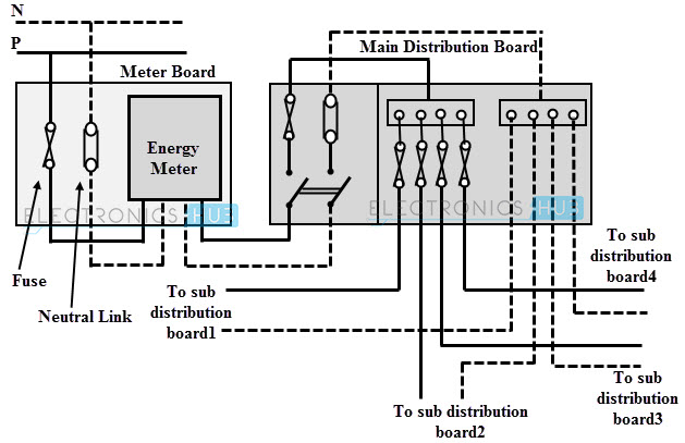
The intended use of the drawing dictates the level of detail provided by each block. Block diagrams are the simplest type of drawing. The uses of these two types of diagrams are compared in table 1. There are three ways to show electrical circuits. The wiring diagram shows the interconnection wiring between the. The two most commonly used are the wiring diagram and the schematic diagram.
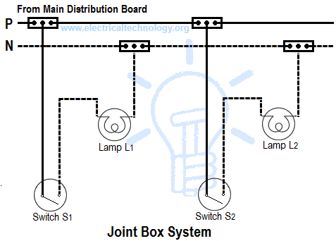
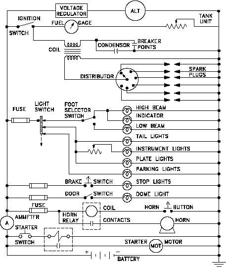
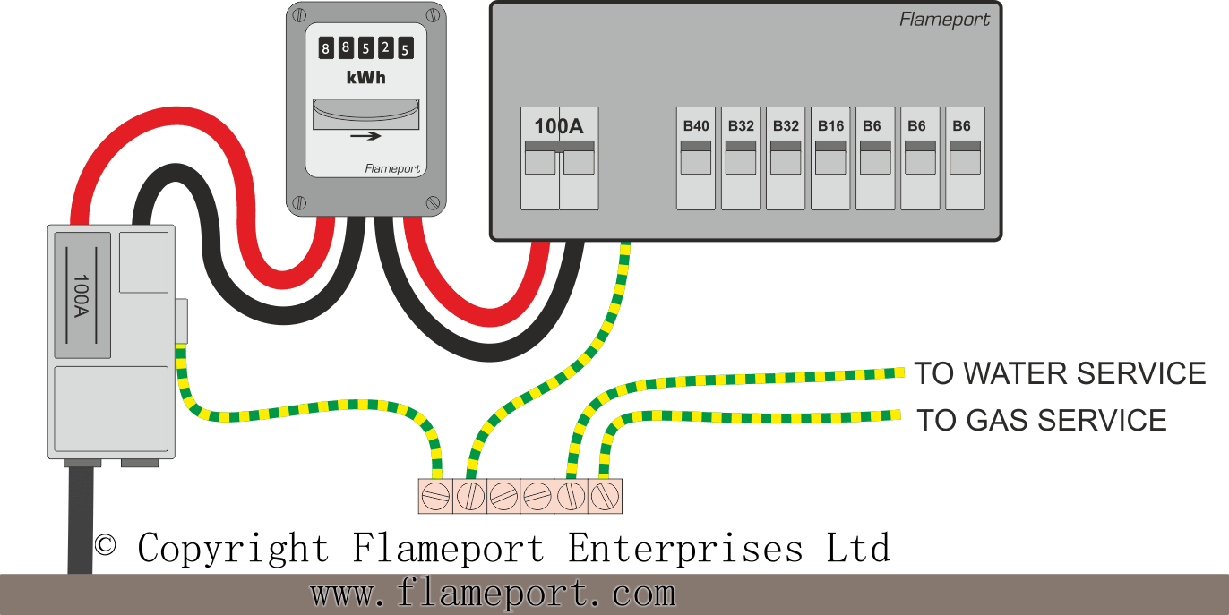
As the name implies block diagrams represent any part component or system as a simple geometric shape with each block capable of representing a single component such as a relay or an entire system. Electrical info types of diagram. In addition they will understand. Figure 9 provides a simple example of how a schematic diagram compares to a pictorial. It shows the wiring between the elements that lines represent the wire and is marked with numbers or letter combinations. Drag the shape that you need directly onto the canvas.
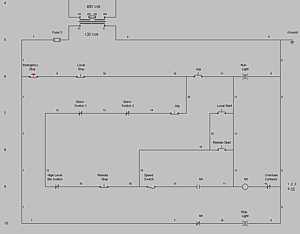
A ladder diagram may also be referred to as a line diagram elementary diagram or. Of all the different types. Types of electrical diagrams or schematics. Schematic diagrams schematic electrical wiring diagrams are different from other electrical wiring diagrams because. Ladder or line diagram. A diagram of a system in which the principal parts or functions are represented by blocks connected by lines that.
They are wiring schematic and pictorial diagrams. Ladder diagrams allow a person to understand and troubleshoot a circuit quickly. Using the symbols a wiring diagram is drawn these symbols represent the devices of the electrical control panel. Ladder or line diagram a ladder or line diagram is a diagram that shows the function of an electrical circuit using electrical symbols. It is a simplified. This article will review the basic symbols and conventions used in both types of drawings.
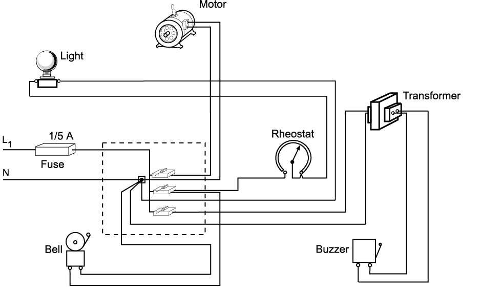
The pictorial diagram is usually not found in engineering applications for the reasons shown in the following example. Wiring diagrams are used by equipment manufacturers to install wires in electrical equipment such as switchboards and panels. Basic electrical circuits and theory branch circuit wiring a basic top view floor plan terminology block diagram.

