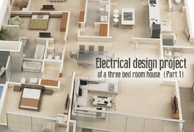
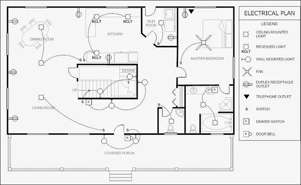
That part of the earthing system which interconnects the overall metallic parts of electrical installation eg. Diagrams will show receptacles lighting interconnecting wire routes and electrical services within a home.
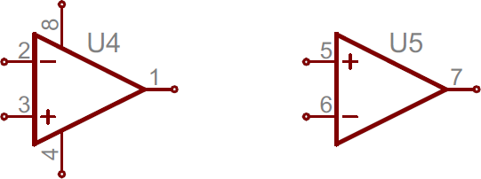
How To Read A Schematic Learn Sparkfun Com
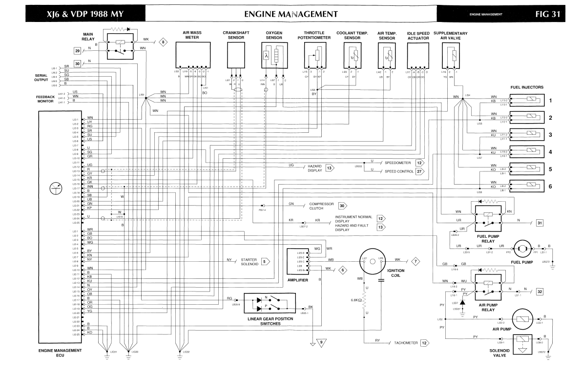
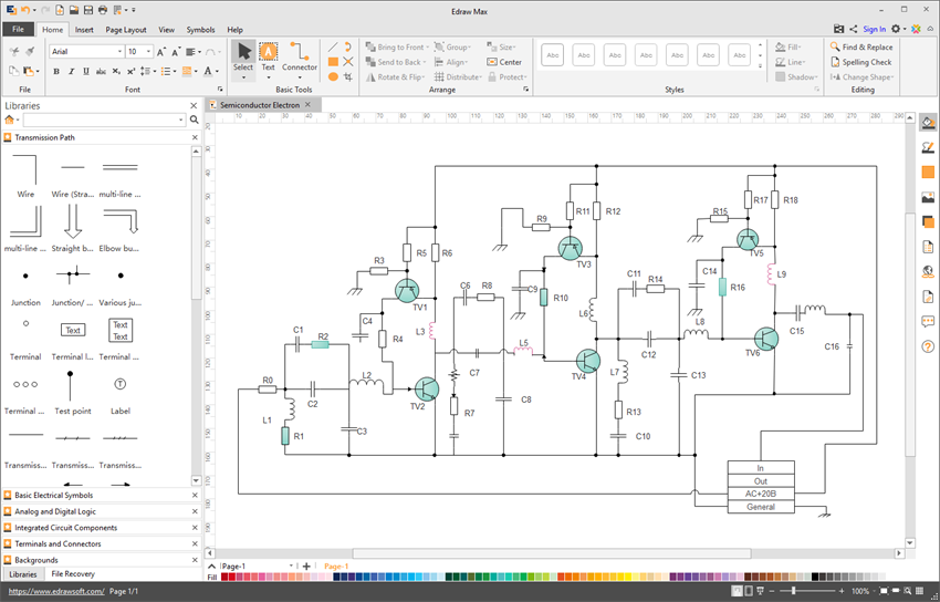
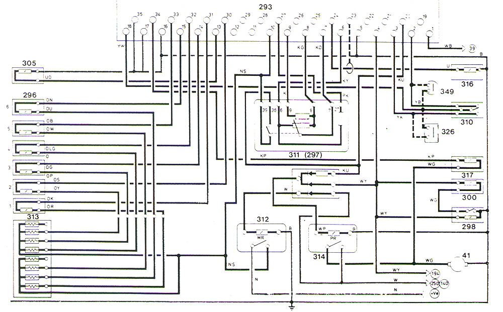
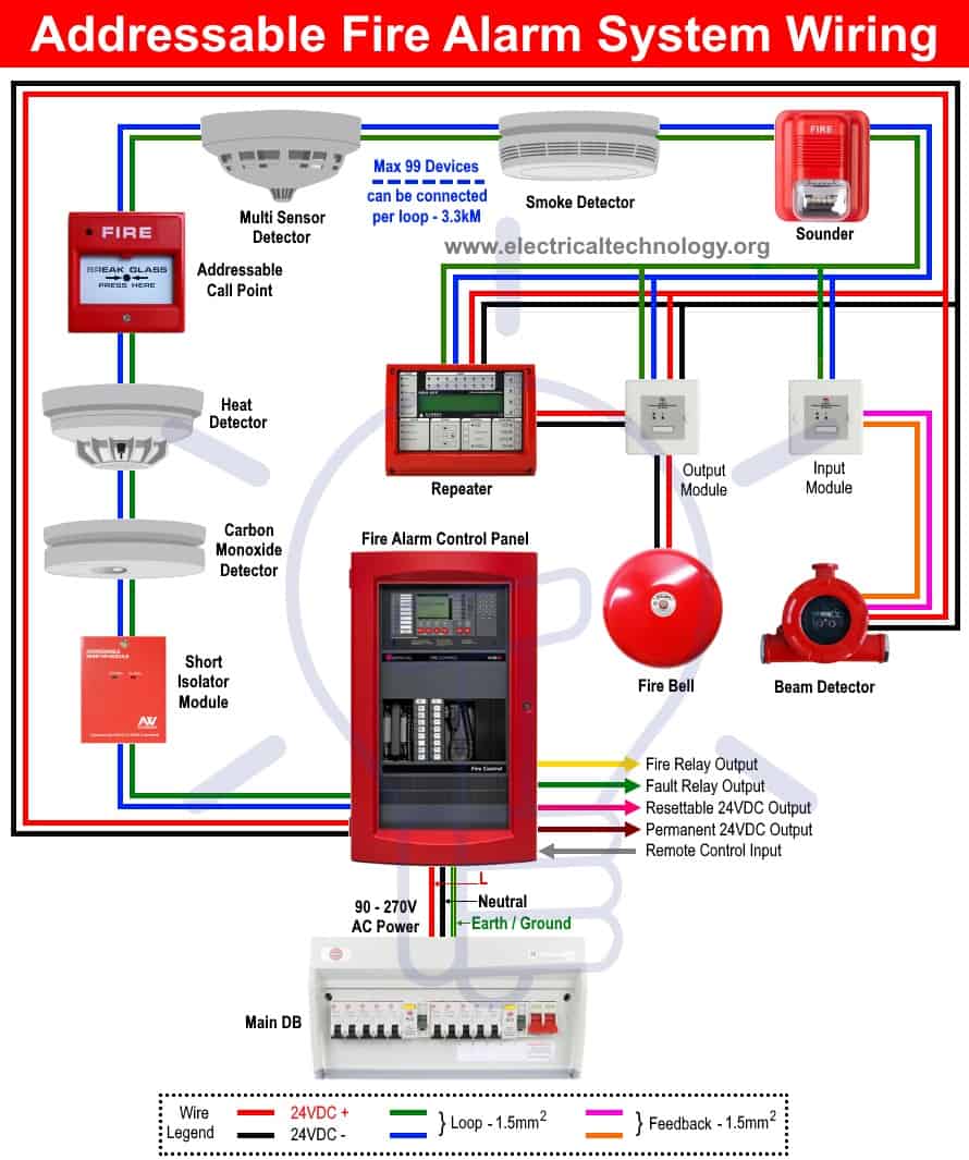
Types of electrical diagrams pdf. Ladder diagrams allow a person to. The wiring diagram shows the interconnection wiring between the electrical equipment. In addition they will understand. Basics 16 wiring diagram. Basics 17 tray conduit layout. Electrical info types of diagram.
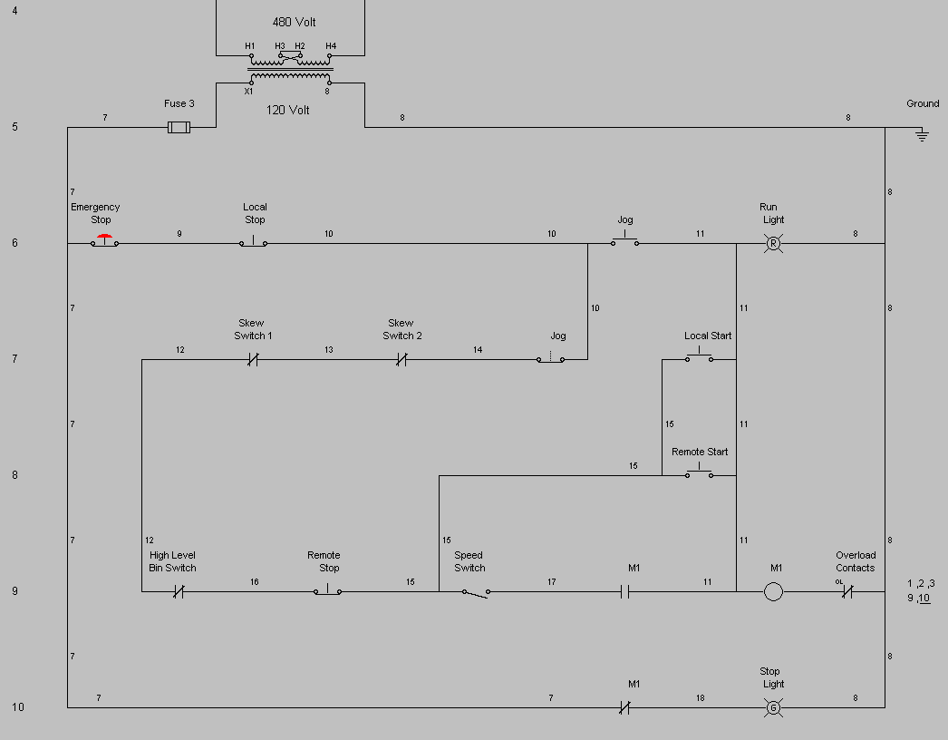
This includes circuit breaker boxes and any alarms that are wired into the system. Components of electrical earthing system earth continuity conductor or earth wire. Ladder or line diagram a ladder or line diagram is a diagram that shows the function of an electrical circuit using electrical symbols. Fiber optic cable electrical connections boundary seal to be in. Some of these are discussed below. Lines are used to represent a single carrier multiple conductors installed in the same channel are shown as a single line with radial branches and the conductors representation is labeled with the identification number.
9102010 104223 am. From the main switchboard various types of electrical loads such as fans lights room coolers and refrigerators are connected through the wiresthere are different types of wirings used for connecting the loads to the mains which can be used for house electrical wiring as well as industrial electrical wiring. Understand the difference between different types of diagrams know how to draw a basic floor plan with electrical symbols assumptions students will have been introduced to electrical equipment and terminology. Typical electrical drawing symbols and conventions. These diagrams show the functional apparatus at their appropriate relative physical locations. Cleat wiring methods of electrical wiring systems wrt taking connection.
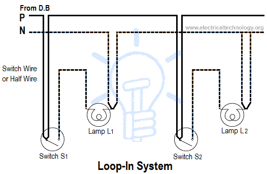
Wiring diagram book a1 15 b1 b2 16 18 b3 a2 b1 b3 15 supply voltage 16 18 l m h 2 levels b2 l1 f u 1 460 v f u 2 l2 l3 gnd h1 h3 h2 h4 f u 3 x1a f u 4 f u 5 x2a r power on optional x1 x2115 v 230 v h1 h3 h2 h4 optional connection electrostatically shielded transformer f u 6 off on m l1 l2 1 2 stop ol m start 3 start start fiber optic transceiver class 9005 type ft fiber optic push button selector switch limit switch etc. Basics 19 instrument loop diagram. Ladder or line diagram. Loop in or looping systemcasing and capping wiringbatten wiring cts or trslead sheathed wiringconduit wiringsurface conduit wiringconcealed conduit wiringtypes of conduitmetallic conduitnon metallic conduitsize of conduitcomparison between different wiring systems. Different switches and different types of outlets all have different symbols and youll need to know these symbols in order to be able to read an electrical wiring diagram. Conduit ducts boxes metallic shells of the switches distribution boards switches fuses regulating and controlling devices metallic parts of electrical machines such as motors generators transformers and the metallic framework where electrical devices and components are installed is known.
In this porcelain wood or plastic cleats are fixed to walls or ceilings at regular intervals ie 06 m between each cleat. Basics 18 embedded conduit layout. It does not show the actual locations of the components. An electrical diagram is helpful in understanding how a circuit works and trouble shooting it. An electrical wiring diagram will use different symbols depending on the type but the components remain the same. A diagram of a system in which the principal parts or functions are represented by blocks connected by lines that.
Joint box or tee or jointing system. Types of electrical diagrams. Basic electrical circuits and theory branch circuit wiring a basic top view floor plan terminology block diagram. Ladder or line diagram wiring diagram and one line diagram. What is electrical wiringdifferent types of electrical wiring systems.
