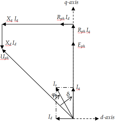
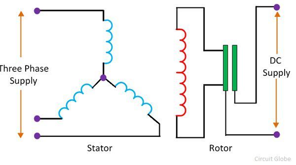
Model diagram and phasor diagram of synchronous motor field structure is stimulated by direct current in synchronous motor. So the attraction force develops between them.
How To Control Ac Synchronous Motor
Synchronous motor wiring diagram. The type number identification system for slo syn synchronous motors is straightforward and easily understood. The stepping motor is transformed into a synchronous motor by replacing the wound wire for the ac power specification. The non unidirectional torque pulsates the rotor only in one place and because of this reason the synchronous. The same pole of the stator and rotor face each other and the force of repulsion develops between them. In stator winding two effects are to be considered the effect of field cutting stator conductors at synchronous speed and the effect of stator revolving field. Phasor diagram of salient pole synchronous motor for phasor diagram.
Asked jul 12 2020. 10 model diagram of synchronous motor. In case of a synchronous motor revolving field structure is to be energized by direct current dc current. Questions are typically answered within 1 hour see solution response times may vary by subject and. For simplicity consider the motor has two poles. Phasor diagram of salient pole synchronous motor for phasor diagram checkcircle expert answer.
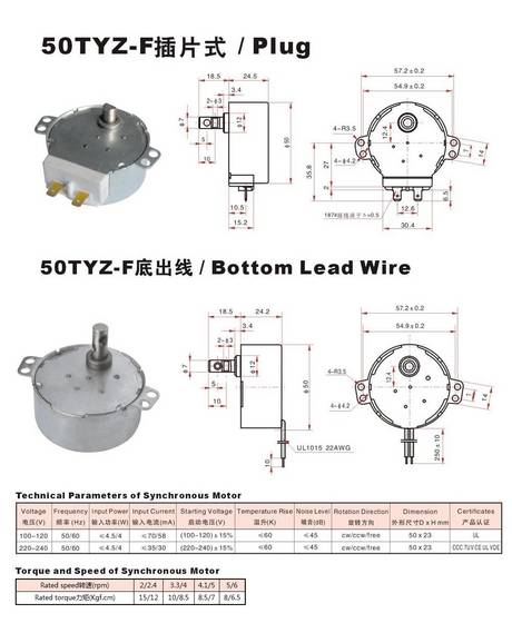
For example in type number ss25 the ss indicates standard slo syn which has a synchronous shaft speed of 72 rpm at 120 volts 60 hertz. You could come from an internet search engine after that discover this website. These motors have a position sensor integrated within the motor which provides a low level signal with a frequency proportional to the speed of rotation of the motor. Want to see this answer and more. Solutions are written by subject experts who are available 247. V terminal voltage r e effective resistance x l leakage reactance x a fictious reactance x s synchronous reactance e counter emf.
Let understand this with the help of the diagram. Whatever you are we attempt to bring the web content that matches just what you are trying to find. Or you are a trainee or maybe even you who simply wish to know concerning asynchronous motor wiring diagrams. The 25 in the type number designates the torque rating of the motor in ounce inches. Figure 4 shows the letter designations which are offered and figure 5 shows how the two elements of the type number identify the. Check out a sample qa here.
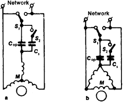
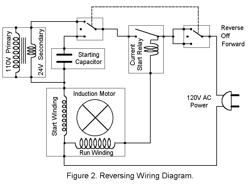
Want to see the full answer. This subject is a great deal of people browsing on the internet for that reason we accumulate. Service application manual sam chapter 620 37 section 6a terminal markings and internal wiring diagrams single phase and polyphase motors. 800 x 600 px source. In the below figure the opposite pole of the stator and rotor face each other. After the half cycle the poles on the stator reverse.
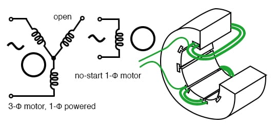
By circuit diagram a synchronous electric motor is an ac motor distinguished by a rotor spinning with coils passing magnets at the same rate as the alternating current and resulting magnetic field which drives it. The alternating current windings of two phase alternating current generators and synchronous motors shall have terminal markings as given in mg 1 266 for two phase single speed induction motors the alternating current windings of single phase alternating current generators and synchronous motors shall have terminal markings as given in fig. Split phase ac induction motor operation with wiring diagram for size. Due to the rotating magnetic field the voltage induced in the stator winding and this voltage is called counter emf e. The block diagram shows the drive electronics associated with a low voltage 12 v dc synchronous motor.
Gallery of Synchronous Motor Wiring Diagram