How to wire an electrical panel square d duration. I use a vacuum motor electric lawn mower and treadmill motors to demonstration some cheap options for speed control and wiring to the wall.

Three Wire Control Circuit With Indicator Lamp
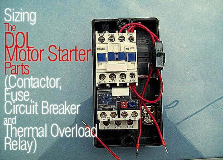
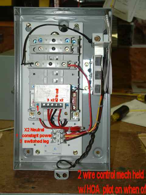
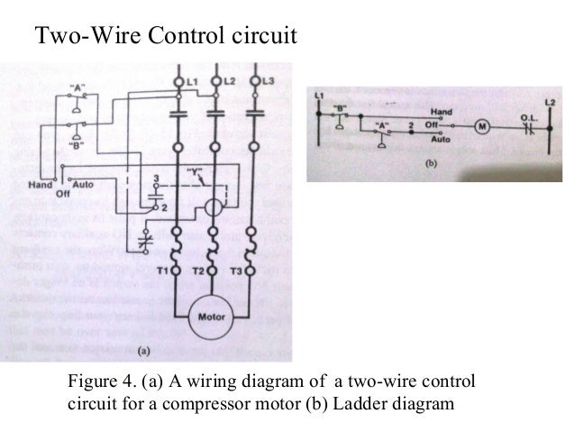
How to wire a motor control. Three phase motor connection schematic power and control wiring installation diagrams. Control circuits can be divided into two major types. Two wire control circuits and three wire control circuits. Assembly your own direct on line motor starter. A two wire control circuit can be a simple switch that makes or breaks connection to a motor figure 18 1. Pete vree 325604 views.
In north america an induction motor will typically operate at 230v or 460v 3 phase 60 hz and has a control voltage of 115 vac or 24 vdc. Star delta y δ 3 phase motor starting method by automatic star delta starter with timer. Used in three phase motors. Ladder diagram basics 3 2 wire 3 wire motor control circuit duration. Wiring diagrams sometimes called main or construction diagrams show the actual connection points for the wires to the components and terminals of the controller. Step by step guide how to wire contactor and motor protection switch.
A good example of this type of control is the single phase manual starter shown in figure 3. Wiring a dc motor and universal motor for speed control. A motor starter is a combination of devices used to start run and stop an ac induction motor based on commands from an operator or a controller. Wiring diagrams show the connections to the controller. The resistance in the sensor remains relatively low and constant over a wide temperature band and increases abruptly at a pre determined temperature or trip point. The thermistor has to be connected to a control circuit which can convert the resistance signal which again has to disconnect the motor.
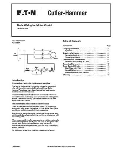
Three phase motor connection stardelta without timer power control diagrams. Like subscribe and dont skip the ads facebook subscribe our page to. Basic wiring for motor control technical data.


