Ebay product id epid 1975950769. 1170 fast n free.

4 Wire Ac Motor Wiring 4 Wire Condenser Fan Motor Wiring
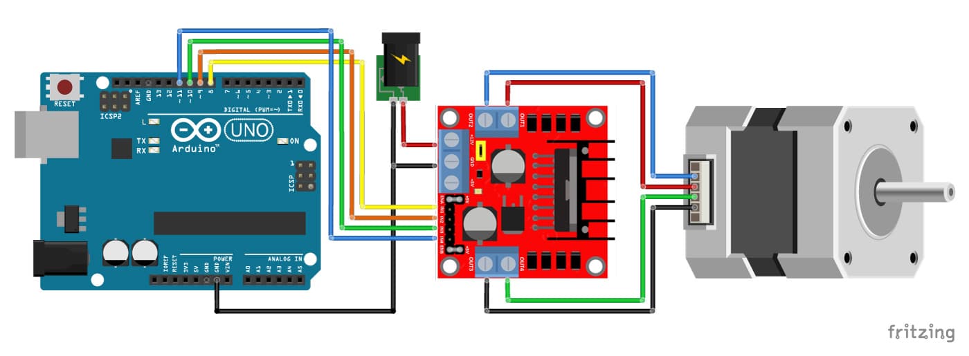
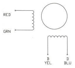
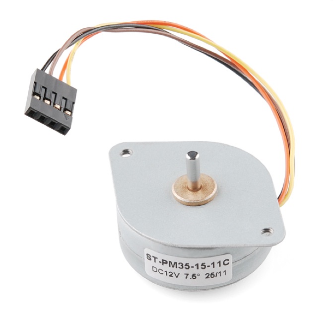
Dc motor 4 wires. How stepper motor stepper controller and stepper driver work 4 wires bipolar motor example. 1 product rating write a review about this product. A basic 4 wire stepper motor is shown in figure 1. Typical voltages for a stepper might be 5v 9v 12v 24v. A wiring diagram is a streamlined conventional pictorial representation of an electrical circuit. When you need to control a dc motor such as a dc linear actuator you usually need to be able to swap the polarity on the wires going to the motor.
Now for your 4 wire method. Higher than 24v is less common and frankly above that its best not to guess. 1 to 2 or 3 to 4 and slowly raise the voltage until the motor is difficult to turn. A double pole double throw switch is used for this purpose but you have to wire it up correctly. It is possible to damage a motor this way so dont go too far. Each of these wires serves a specific purpose.
Actual rated input voltage. Wellborn collection of dc motor wiring diagram 4 wire. As you might have noticed your salvaged hdd bldc motor has four connection leads instead of the said three wires a b c often marked as u v w. Ideally youll know the voltage from the manufacturer but if not get a variable dc power supply apply the minimum voltage that the supply can generate voltage across two wires of a coil eg. 5 pcs 2 phase 4 wire micro stepper motor with cable 3 5v dc dia 8mm mini steppin. Dc motor wiring diagram 4 wire october 15 2018 by larry a.
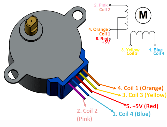
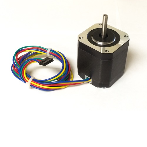
Nominal rated input voltage. Oh its a 4 wire hdd bldc motor. 4 wire stepper motors while many motors take advantage of 6 and 8 wire configurations the majority of bipolar one winding per phase stepper motors provide four wires to connect to the motor windings. A 4 wire cpu motherboard fan is a standard brushless dc bldc fan but has four wires extending from the casing. Wire a dpdt rocker switch for reversing polarity. White wire from the condenser fan motor to one side of power on the contactor t1 black wire from the condenser fan motor to other side of power on the contactor t2 brown wire from the condenser fan motor to the capacitor.
You can see the cross section of a 3 phase brushless dc motor in the image provided below.

