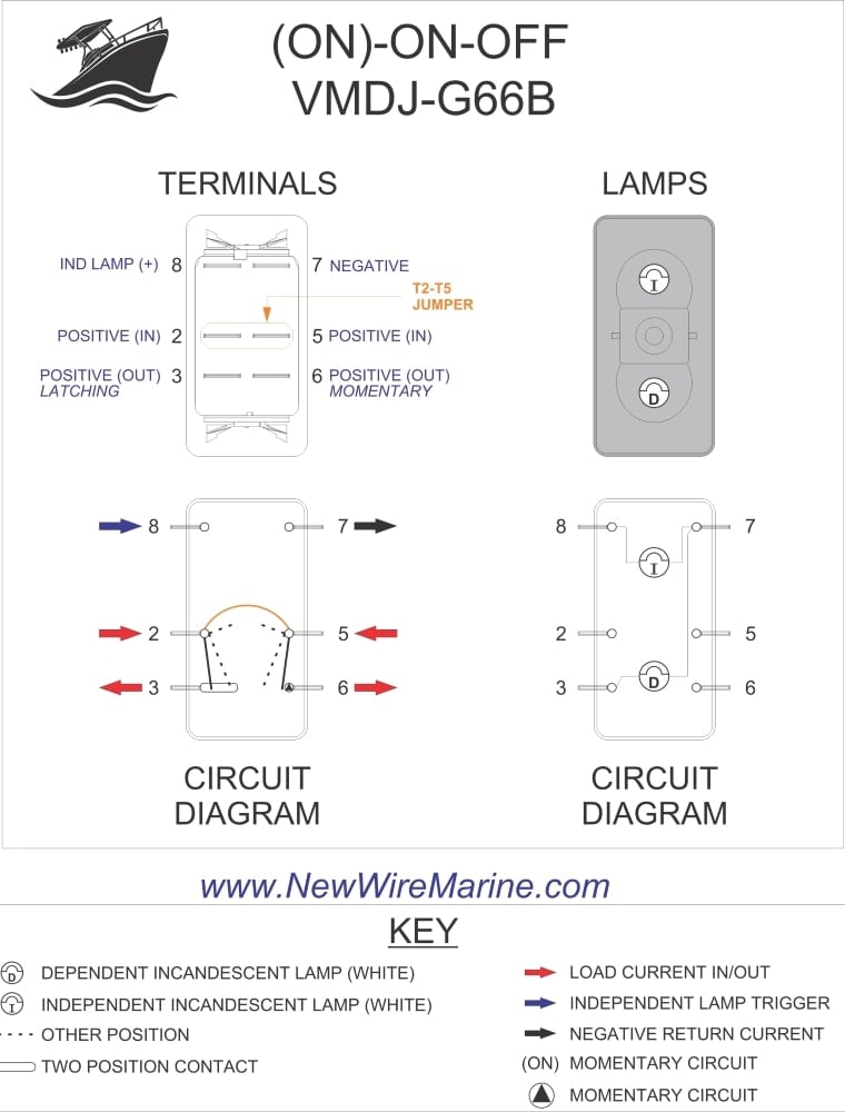
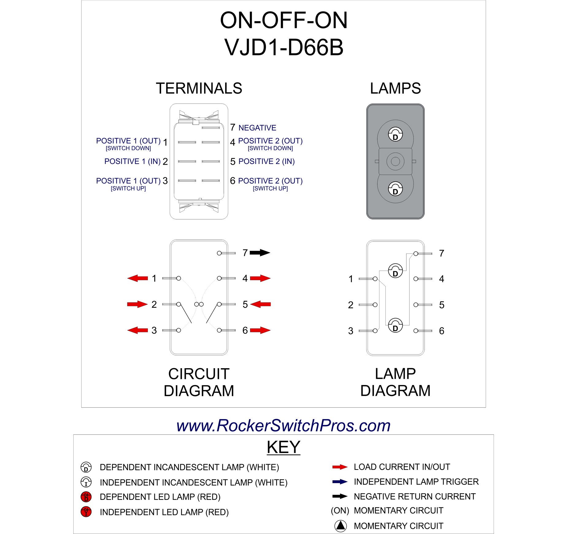
We also carry a four prong v1d1 rocker switch with two lights pn. This switch will replace a v1da rocker switch as well which has plastic barriers between the terminals on the back.

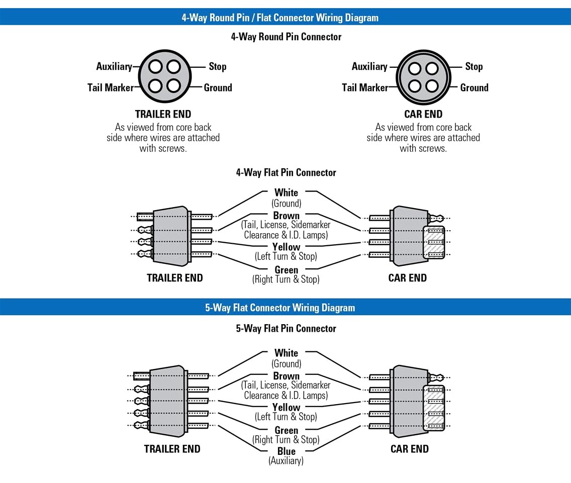
Trailer Wiring Diagram Lights Brakes Routing Wires
5 prong switch wiring diagram. In this video i show you how to wire a dual led rocker switch. 5 pin rocker switch wiring diagram. Riding lawn mower ignition switch wiring diagram lawn mower ignition switch wiring diagram elegant lawn mower ignition wiring diagram melissatoandfro 15. Sol terminal on ignition switch relay trigger ground wire to a good chassis ground starter solenoid page 1 wires power directly to headlights through relay uses existing headlight switch to control a power relay maximizes voltage to headlights maxxforce dt 9 10 2010 2013 engine wiring diagram page 2 of 3 86 pin connector 6341 53 pin connector 6340 twisted pair red b battery voltage red high side driver control blue vref 5 volts green green ac speed signal signal brown. How to wiring the cable of 5p industrial sockets and plugs. With just a few small jumpers our switch selection can be used for a multitude of different functions.
Take the insulation wires and strip about inch on the ends. Variety of on off on toggle switch wiring diagram. Wiring diagram sheets detail. 5 pin power window switch wiring diagram wiring diagram is a simplified suitable pictorial representation of an electrical circuit. The starter wire will connect to an inline fuse before continuing to the starter in the engine compartment. Click on the image to enlarge and then save it to your computer by right clicking on the image.
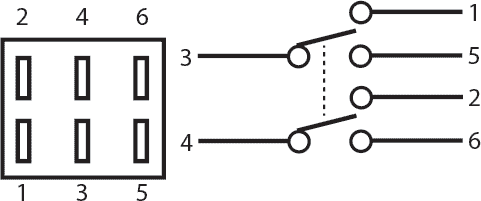
Now that you have an idea how rocker switches are constructed internally lets go over the wiring diagram so. It was introduced commercially in 1989 and became ieee standard 8023 in 1983. North america pin and sleeve. On off on toggle switch wiring diagram telecaster wiring diagram download. This article shows how to wire an ethernet jack rj45 wiring diagram for a home network with color code cable instructions and photosand the difference between each type of cabling crossover straight through ethernet is a computer network technology standard for lan local area network. Consult the diagram on the fusebox to identify the wires by which fuse connects to them.
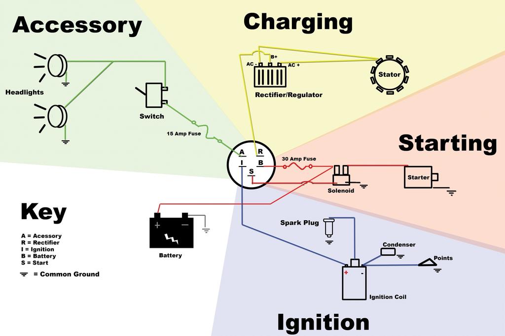
One pin is obviously the earth and the other three are labelled l1 l2 and l3. Identify the five wires to be connected to the ignition switch. This makes it very easy to see your switches at night. This switch body can be paired with many of our printed marine labeled snap in rocker switch. The dual led allows you to illuminate part of the switch with your dash lights. Yugoslavian countries they are 5 pin 3 phase connectors rated at 16 a 380 v.
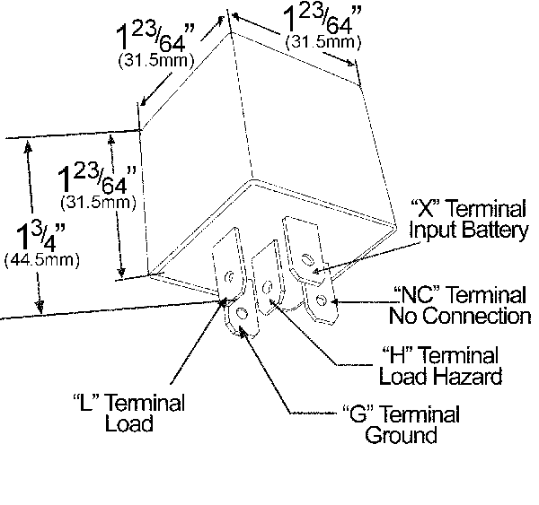
See our v1d1 wiring overview video here. Strip a 14 inch of insulation of each wire. 5 pin relay wiring diagram 5 pin relay wiring diagram 5 pin relay wiring diagram 87a 5 pin relay wiring diagram driving lights every electric structure is composed of various unique components. I had nothing to do so i made this quick how to video. Like all of our rocker switches this is a genuine carling contura v series rocker switch and it is ip68 sealed dustproof and waterproof. The battery wire will trace back to the fusebox as may the accessory wires.
Headlights wiper switch radio. Trace each wire to either the fuse box or its connected accessory ie. V1d1 g66b which can be found below. 3 phase 5 pin plug wiring diagram. It shows the components of the circuit as simplified shapes and the capability and signal links in the middle of the devices.

