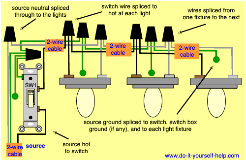
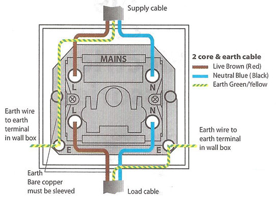
I show how to wire a double switch with 2 single pole switches. 2 pole toggle switch wiring diagram exactly whats wiring diagram.
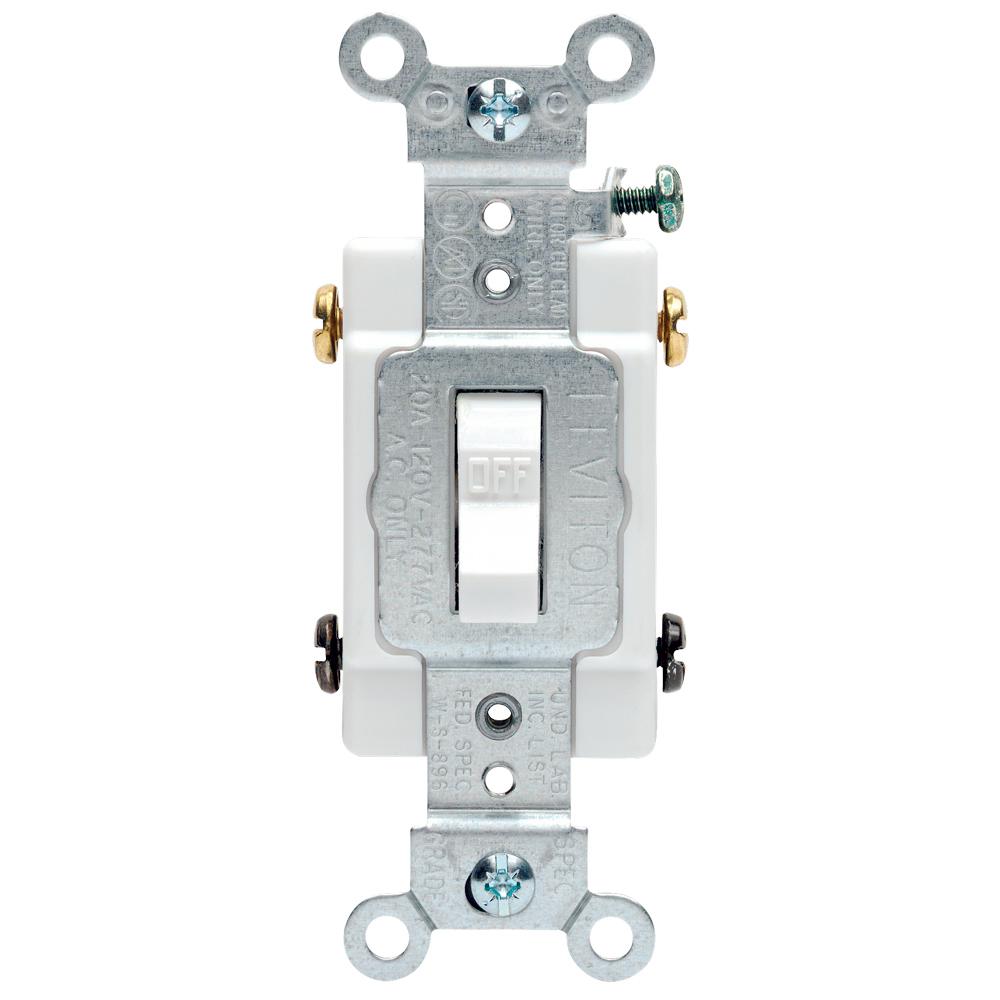
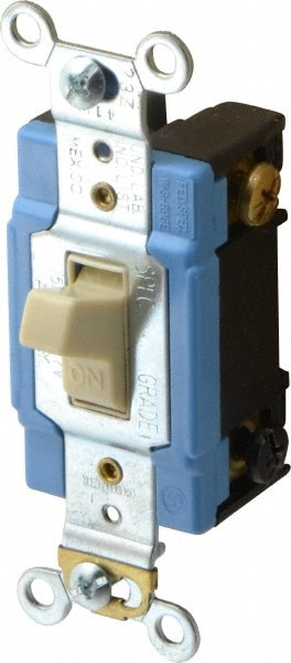
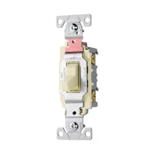
Leviton 20 Amp Commercial Double Pole Toggle Switch White
2 pole switch wiring. A double pole single throw dpst switch controls the connections to two wires at once where each wire only has one possible connection. How to wire a single pole light switch duration. Electrical wiring layouts are comprised of 2 things. A wiring diagram typically provides info concerning the family member position and arrangement of devices and also terminals on the tools to help in building or servicing the tool. Signs that stand for the elements in the circuit and also lines that stand for. Variety of 2 pole contactor wiring diagram.
The difference between a single and double pole switch is that the latter controls two circuits at the same time. A wiring diagram is a streamlined conventional pictorial depiction of an electrical circuit. It shows the elements of the circuit as simplified forms and the power and signal links between the gadgets. At this point if the cable has a neutral line both neutral wires are to be. The double pole switch can now be added into the circuit with both colored wires the black. Double switches sometimes called double pole allow you to separately control the power being sent to multiple places from the same switch.
In other words its like two simple switches controlled by a single actuator. It has four terminals. For example you might want to turn on a bathroom light separately from the ceiling fan. A double switch allows you to operate two lights or appliances from the same location. A double pole switch is what you need to control a 240 volt device because 240 volt circuits have two hot wires. It reveals the components of the circuit as streamlined forms and the power and signal links in between the tools.
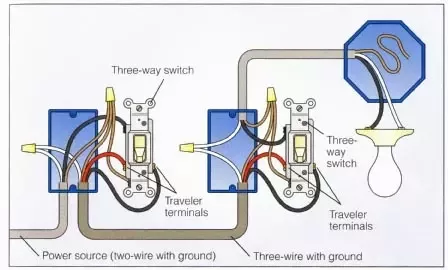
Collection of 2 pole toggle switch wiring diagram. A wiring diagram is a kind of schematic which utilizes abstract photographic icons to show all the affiliations of components in a system. Step 22 connect the cable. Two for incoming hots and two for outgoing hots. A wiring diagram is a simplified traditional photographic depiction of an electrical circuit. Step 22 add the switch.
Step 2 hook up the switch step 21 connect the neutral line.
Gallery of 2 Pole Switch Wiring

