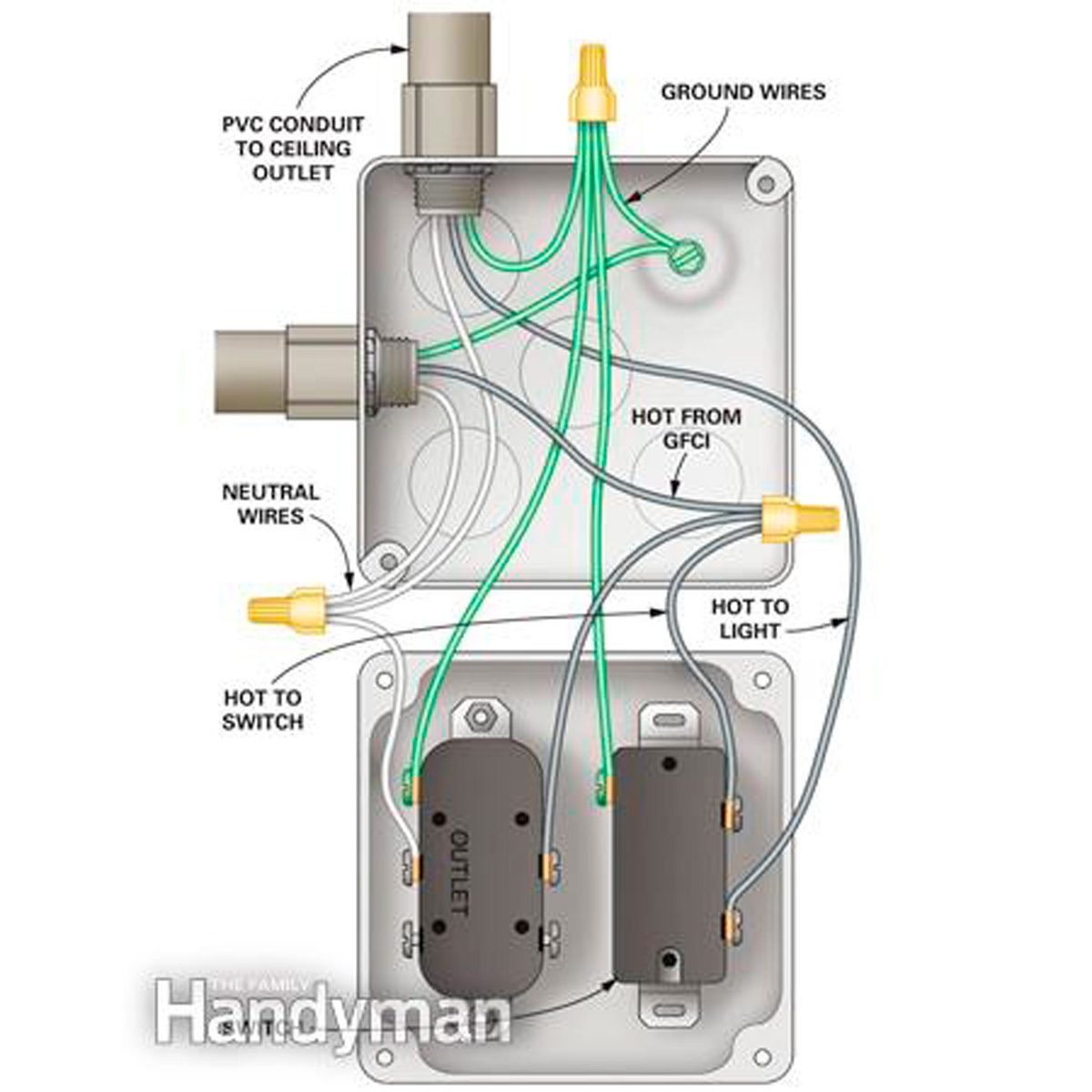
Wiring a gfci outlet with a light switch in the first diagram the single way switch and light bulb is connected to the load terminal of gfci. Locate a nearby electrical outlet or junction box that the recessed light switch and the recessed light will be wired to.

Wiring Diagram For Multiple Lights On One Switch Power
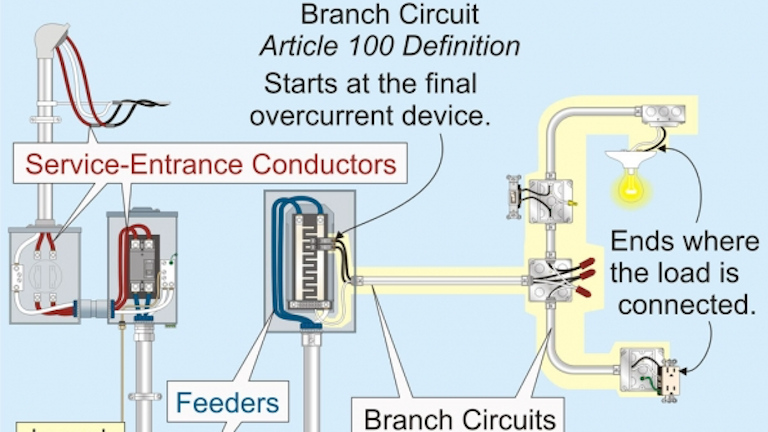
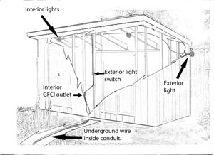
Wiring lights and outlets. This way the switch and light bulb is gfci protected. Wiring lights and outlets it is typical that the room outlets and lights are wired together on one circuit. When wiring a house its always a good idea to put lights and outlets on separate circuits which guarantees that if the outlet circuit fails you still have light. My short answer to the question is that yes lights and power outlets aka ac receptacles can be on the same circuit controlled by a circuit breaker especially in a single family residential house. To be safe test both the top and bottom with the radio. For lights turn the light switch on and off to be sure.
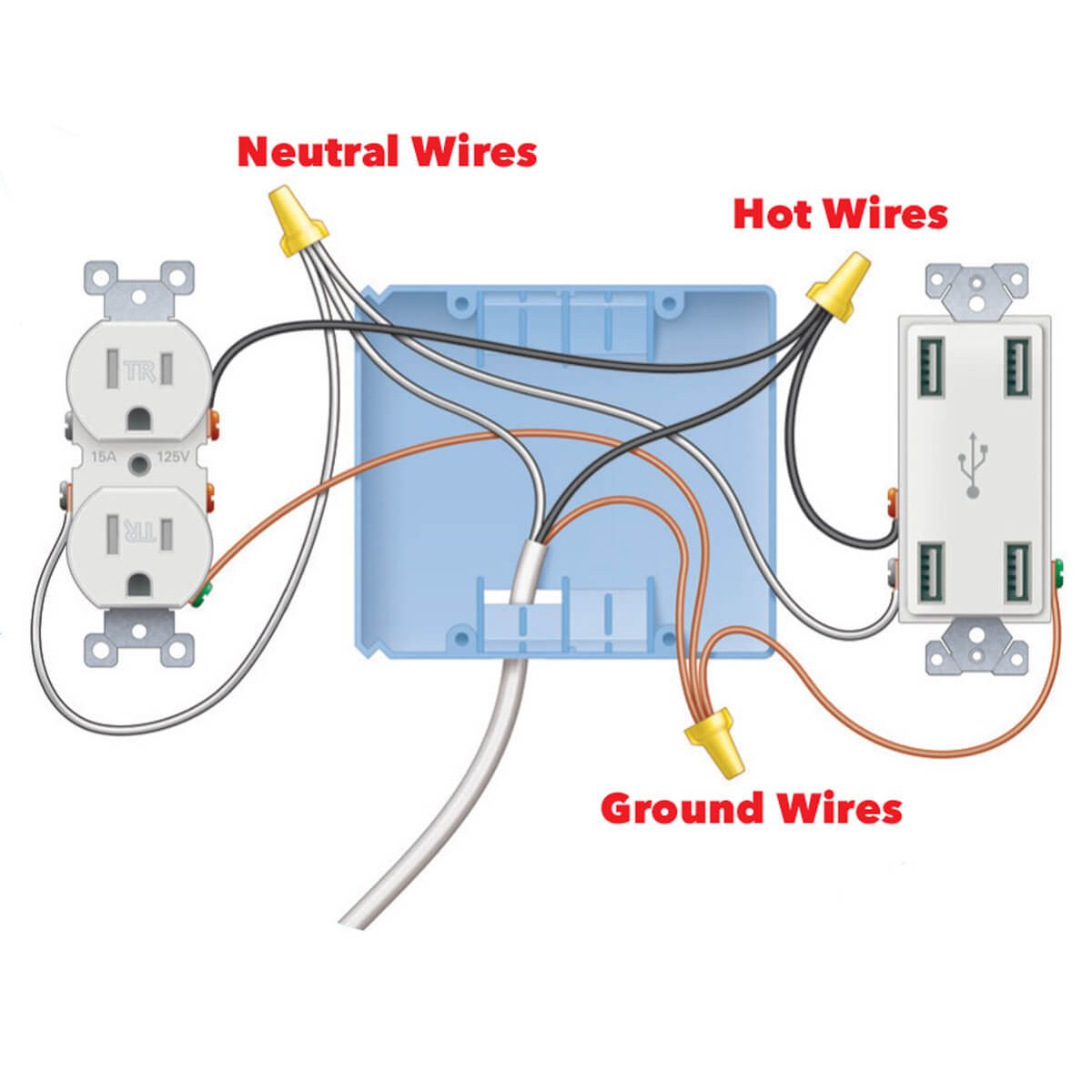
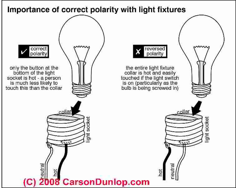
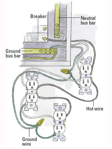
Wiring multiple outlets and a gfci here a gfci receptacle is added at the end of a row of duplex receptacles for single location protection. As long as you dont put too many lights on the light circuit you can usually control that circuit with a 15 amp breaker as well as wire it with a 14 gauge wire. At the light it connects to the neutral terminal. Remove the face plate from the outlet or junction box. With this kind of an illustrative guide you will have the ability to troubleshoot stop and full your projects without difficulty. Some duplex outlets can have different circuits running to adjacent outlets.
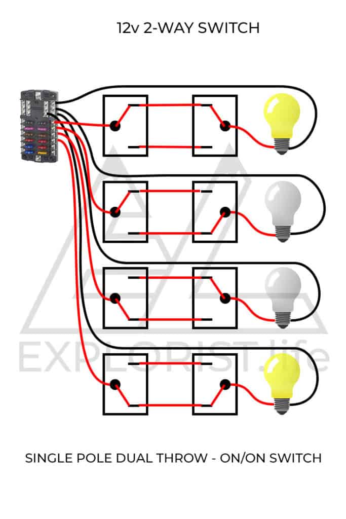
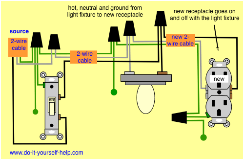
All wires are spliced with a pigtail at the devices to pass current to the next. Before doing any wiring plug the radio into other outlets you plan to work on. Wiring lights and outlets on same circuit diagram you will want a comprehensive professional and easy to know wiring diagram. The first outlet is connected to the source and 2 wire cable runs from box to box. In the second diagram the light switch is connected to the line terminals of gfci. Two wire cable runs from the combo to the light fixture and the switch output is connected to the black wire running to the fixture hot terminal.
The source neutral wire is spliced to the neutral on the receptacle half of the combo device and to the white cable wire running to the light.

