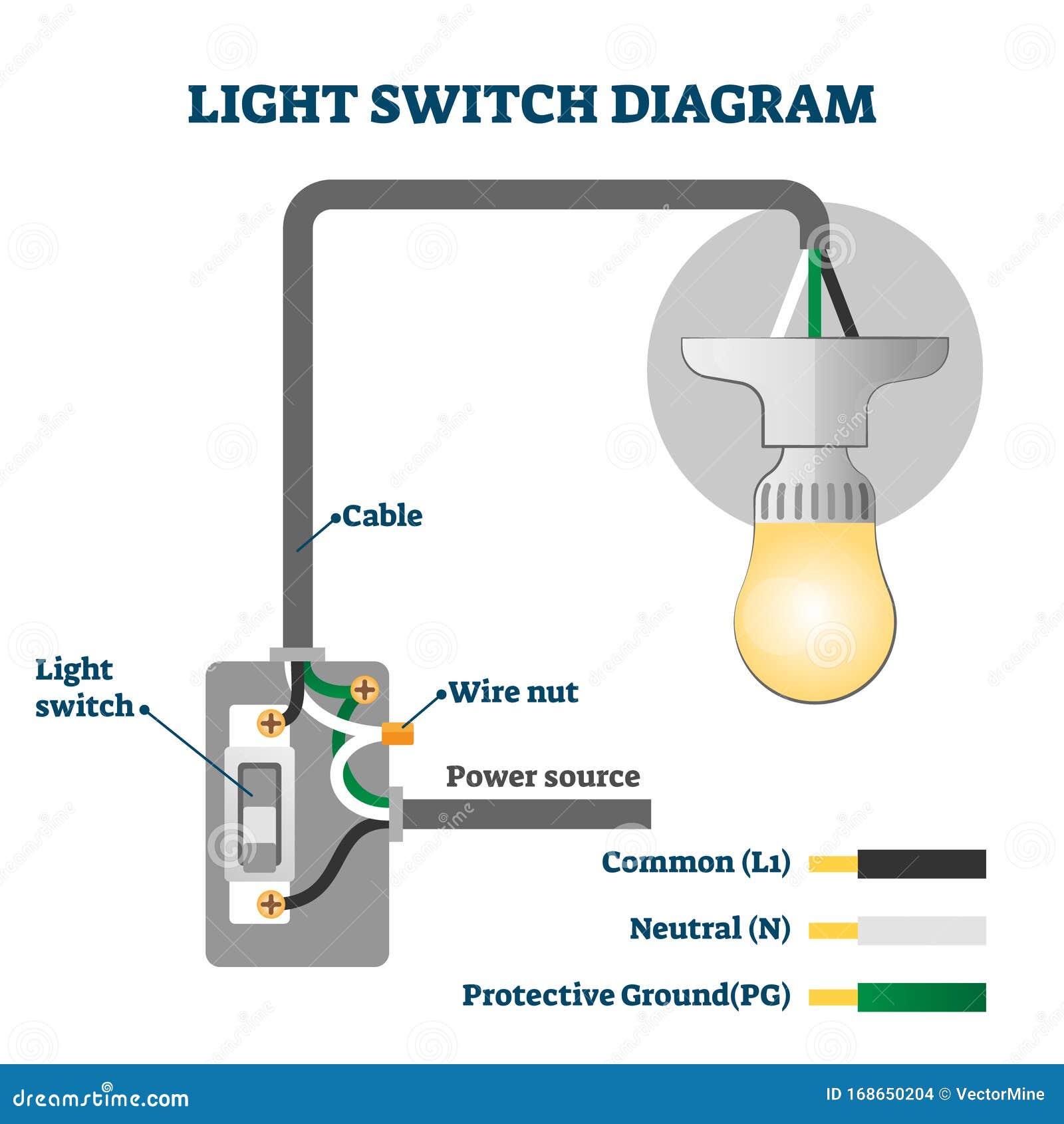
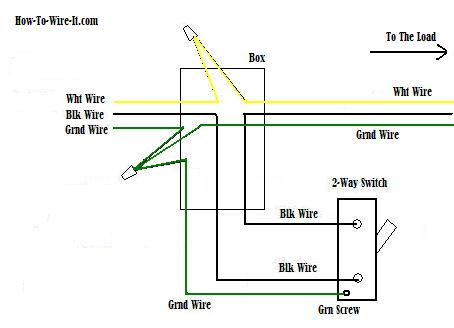
Line diagram of a one way lighting circuit using in line method fig 1. The cable going to the light switch is connected as follows fig 2.
For Single Amp Multiple Lights Wiring Switch Diagrams How To
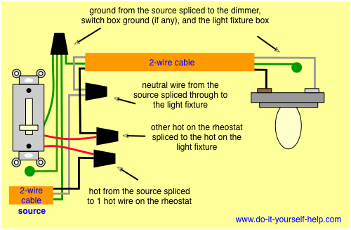
Wiring a light switch diagram. Circuit electrical wiring enters the switch box. Simply strip the wire to the length specified and push the wire into the hole. Here a receptacle outlet is controlled with a single pole switch. The black wire power in source attaches to one of the switch screw terminals. Wiring a single pole light switch. Wiring diagram of a wemo wifi switch with red for load black for line white for neutral and a yellow connected to a green ground wire.
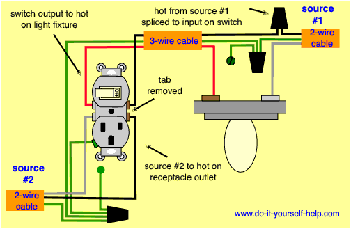
The ground wire from the smart switch needs to be connected to that. The black hot connection is broken to turn the light onoff the white neutral connection completes the circuit. In this diagram 2 wire cable runs between sw1 and the outlet. In this diagram power enters the fixture box. The black wire power out wiring attaches to the other switch screw terminal. The black hot wire connects to the far right switchs common terminal.
This is a diagram of a switch with a neutral. Fixture wiring exits the switch box. A one way light switch is quite easy to wire up. Connect the source wire to the bottom terminal of the switch and the other black wire to the top terminal. Hey doing it yourself is great but if you are unsure of the advice given or the methods in which to job is done dont do it. We have and extensive collection of common light switch arrangements with detailed lighting circuit diagrams light wiring diagrams and a breakdown of all the components used in lighting circuits.
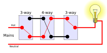
This light switch wiring diagram page will help you to master one of the most basic do it yourself projects around your house. In this picture you can see the strip gauge on the back of the switch. 3 way switch wiring diagram line to light fixtureline voltage enters the light fixture outlet box. Dont forget to take a quick look at the key to wiring diagrams to familiarize yourself with the conventions used on the site. In your switch box you should have one or more grounding conductors spliced together with a wire connector or wire crimp. Red and blue wires link traveler terminals of both switches.
The red wire from the feed cable is connected to the top terminal the red wire going to the light is connected to the bottom terminal the black wires from both cables are connected together in a plastic terminal block and the earth wires are connected to the earth terminal. This is commonly used to turn a table lamp on and off when entering a room. The bare hopefully solid copper wire is the ground. This site is merely. No longer allowed after 2011 nec if no neutral wire in switch boxes 3 way switch wiring diagram light fixture between switchesline voltage enters the first 3 way switch outlet box light fixture is located between switch boxesno longer allowed after 2011 nec if no neutral wire in switch boxes. Wiring a switch to a wall outlet.
This gauge is when you want to use the quick connect method when wiring a light switch. The source is at sw1 and the hot wire is connected to one of the terminals there. Switch wiring shows the power source power in starts at the switch box. This 3 way light switch wiring diagram shows how to do the light switch wiring and the light when the power is coming to the light fixture.


