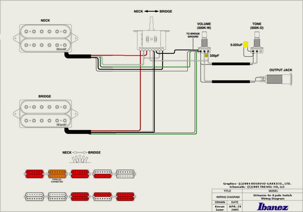
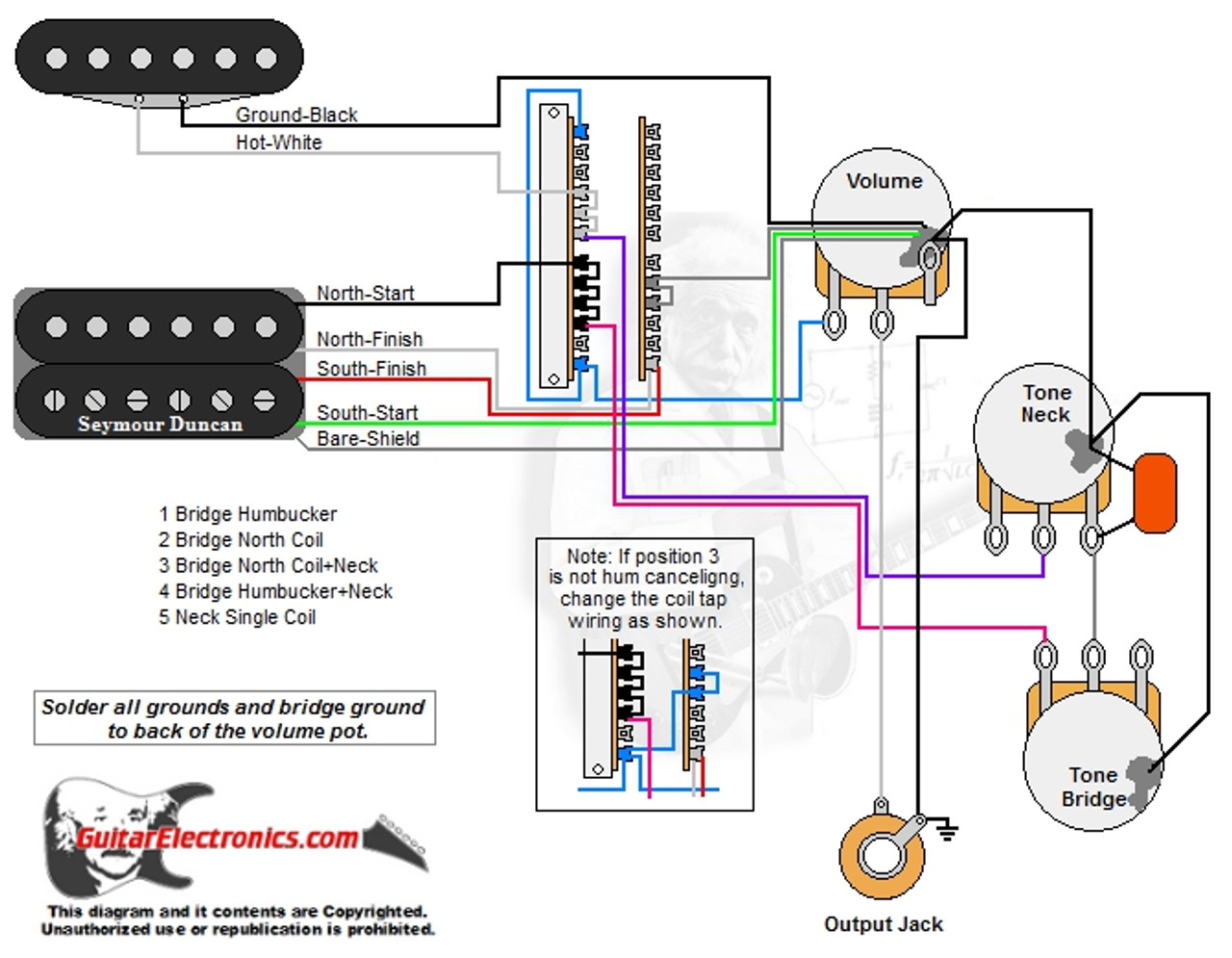
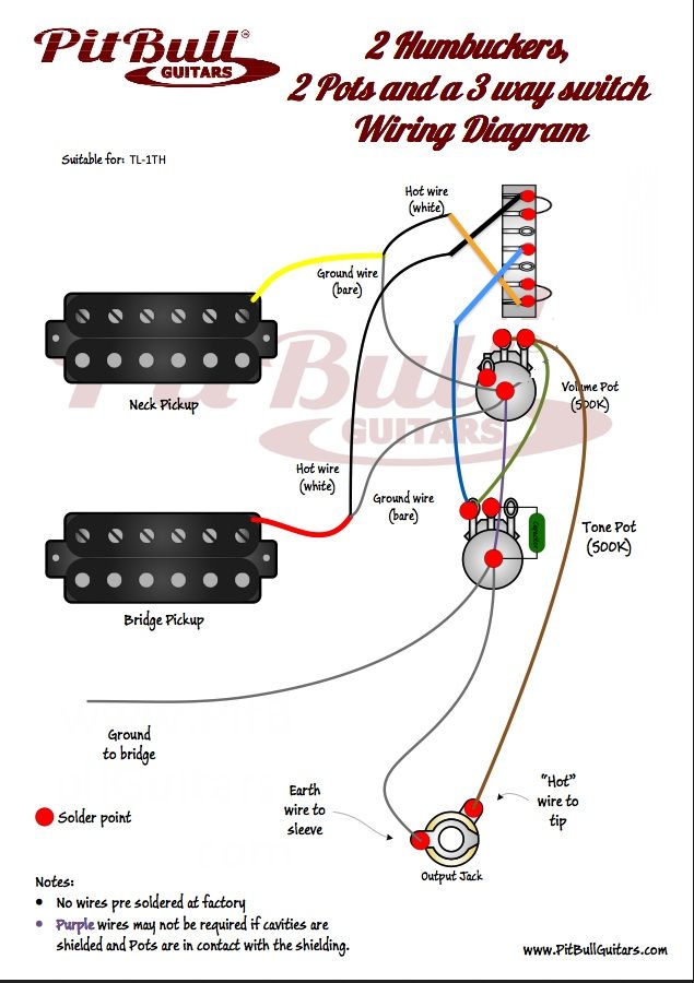
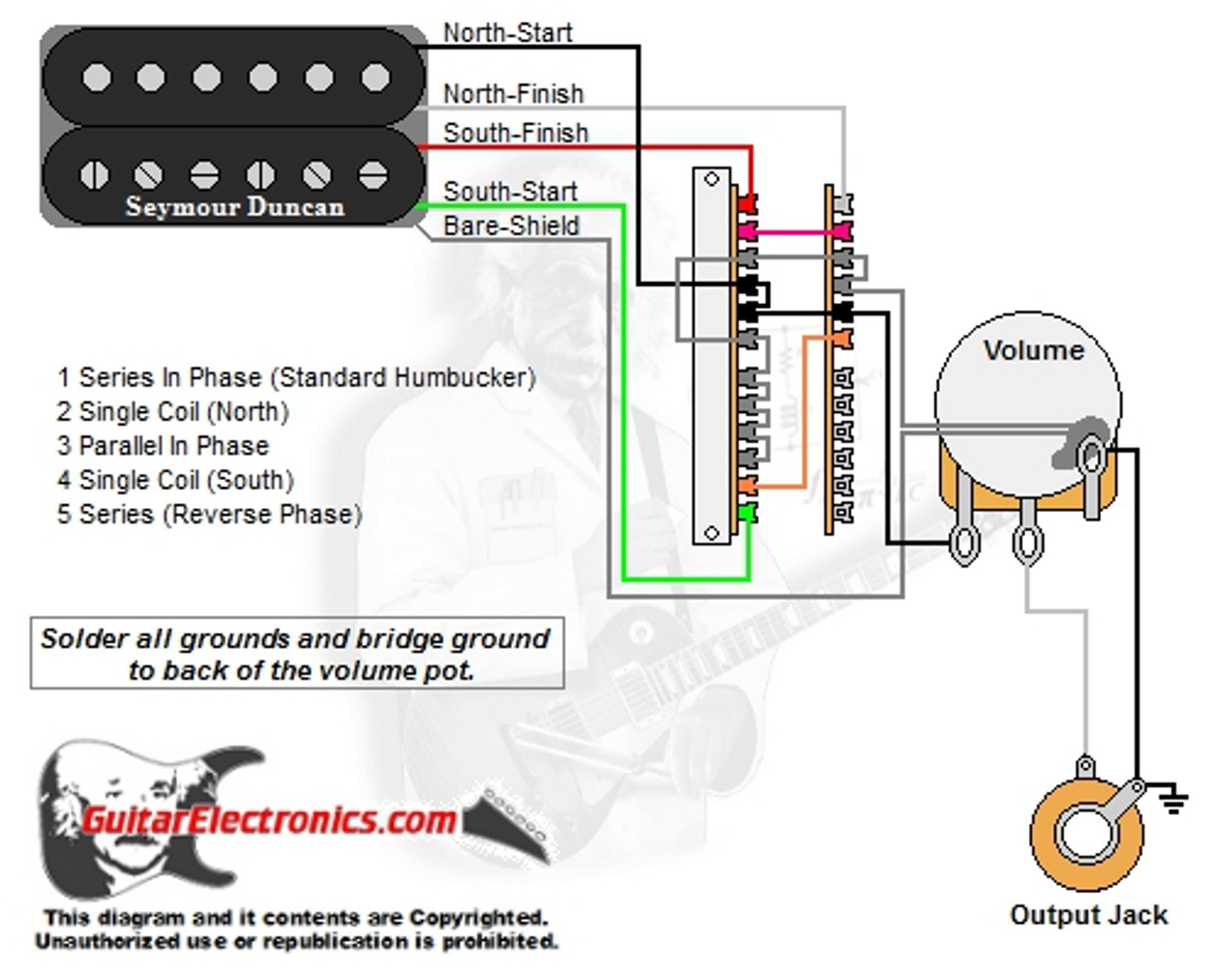
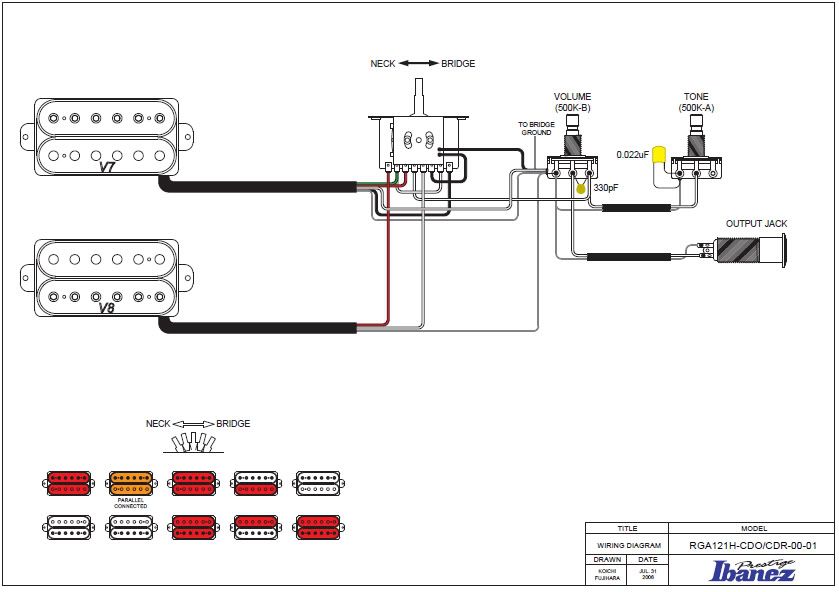
Easy to read wiring diagrams for guitars basses with 2 humbuckers 5 way pickup selector switch. Connecting the 5 way strat switch if you remember from part 1 the anatomy of a 5 way strat switch we have two sides.
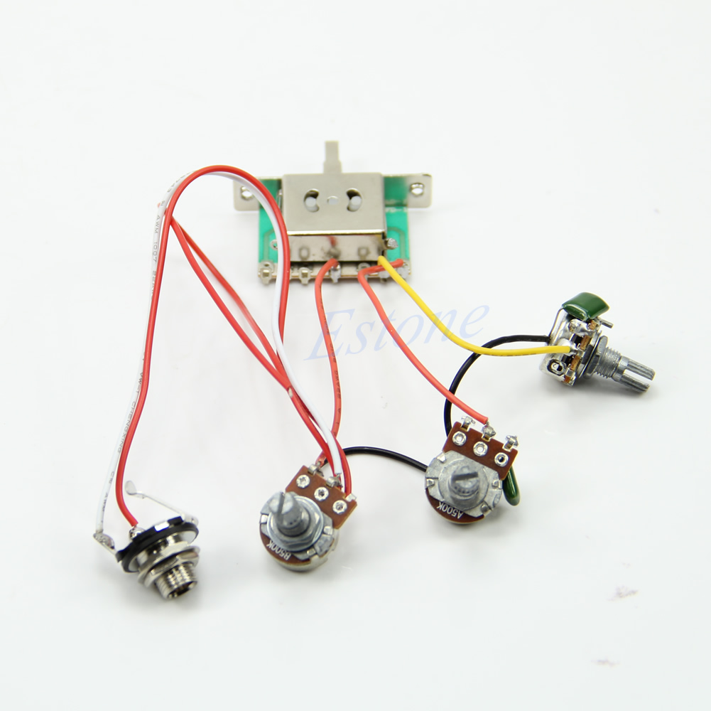
21 Unique Import 5 Way Switch Wiring Diagram
Wiring a 5 way switch. Signs that represent the components in the circuit as well as lines that stand for the. This wiring uses a 5 way switch includes both humbuckers individually and adds tones using coils from both pickups to create other humbucker style tones. A wiring diagram is a kind of schematic which uses abstract photographic signs to reveal all the interconnections of parts in a system. The first element is emblem that indicate electric component in the circuit. There are two things which are going to be found in any import 5 way switch wiring diagram. This plan calls for a 4 pole super switch one mother of a switch to replace the boring ol 5 way in your guitar.
Guitar wiring diagram with 2 humbuckers 5 way 4 pole lever switch one volume and one tone control. This switch has 24 terminals and allows for some pretty creative switching possibilities. A circuit is usually composed by numerous components. Options for northsouth coil tap seriesparallel more. I made sure the large switch fit in the cavity of my guitar or else id have routing to do as well. 3 single coil wiring.
Bill lawrence chose a standard 0022 µf value but feel free to experiment with other values to find your personal favorite the cap connected to the 5 way switch is the phase shifting cap mentioned. The capacitor connected to the tone pot is your typical tone cap. Same 5 pickup configurations as the prs 5 way rotary switching. Stratocaster wiring diagram 5 way switch exactly whats wiring diagram. Typical stock wiring but the flip of a pushpull or mini toggle switch adds rhythmlead and rhythmmiddlelead combinations. If you are using standard humbuckers seymour duncan gibson etc you must mount.
Wiring layouts are made up of two points. First we have to connect both sides of the switch by adding a jumper from terminal a0 to b0 fig 2. Another thing which you will discover a circuit diagram would be traces. Remember a0 and b0 are the common terminals. Pole a and pole b fig 1. The wiring works best with two single coil pickups like standard tele ones.
