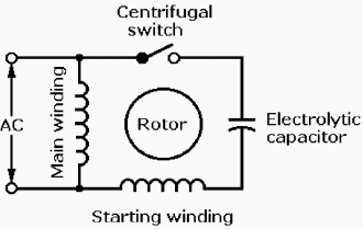
It includes instructions and diagrams for various types of wiring methods and other items like lights home windows etc. Single phase motor wiring diagram with capacitor start.

Internal Wiring Configuration For Dual Voltage Dual Rotation
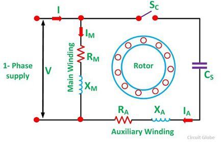
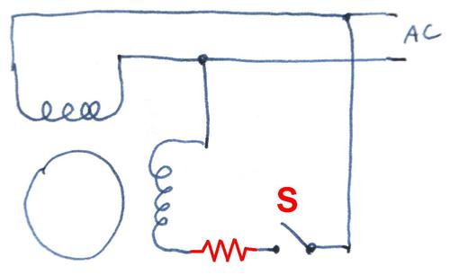
Single phase capacitor start motor wiring diagram. You may be capable to know specifically if the projects ought to be finished that makes it much simpler for you to. Furthermore wiring diagram provides you with enough time body during which the projects are to become finished. However it does not imply link between the cables. How to connect single phase motor. This type of motor is designed to provide strong starting torque and strong running for applications such as large water pumps. According to earlier the lines in a single phase motor wiring diagram with capacitor represents wires.
Single phase motor wiring diagram with capacitor start capacitor run. Frequent stopstarts andor changing of the direction of rotation will damage the motors capacitors and winding. Injunction of two wires is usually indicated by black dot in the intersection of two lines. Types of single phase induction motors electrical a2z single phase induction motors are traditionally used in residential applications such as ceiling fans air conditioners washing machines and refrigerators single phase motor wiring with contactor diagram the plete guide of single phase motor wiring with circuit breaker and contactor diagram. Occasionally the wires will cross. It reveals the components of the circuit as simplified forms as well as the power as well as signal links in between the tools.
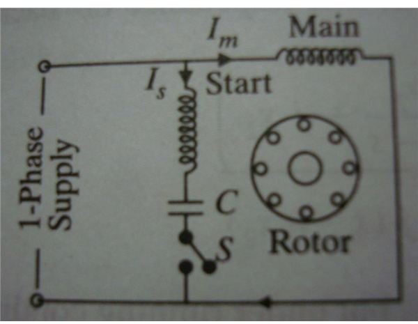
Click here to view a capacitor start motor circuit diagram for starting a single phase motor. L1 and l2 are designated as the two connection points representing the two electricity flow path inherent with single phase circuits where a single phase supply voltage is fed to the motors internal circuit. Variety of single phase motor wiring diagram forward reverse. How to connect single phase single phase motor wiring diagram with capacitor wiring diagram consists of many in depth illustrations that show the link of varied things. The reconnection must be carried out by qualified electrician. Wondering how a capacitor can be used to start a single phase motor.
Wiring diagram single phase electric motor wiring diagram explained motor run capacitor wiring diagram. Capacitor start capacitor run induction motors are single phase induction motors that have a capacitor in the start winding and in the run winding as shown in figure 12 and 13 wiring diagram. Learn how a capacitor start induction run motor is capable of producing twice as much torque of a split phase motor. Wiring diagram single phase motors 1empc permanent capacitor motors 1empcc capacitor start capacitor run motors electric motors limited when a change of direction of rotation is required and a change over switch is to be used it will be necessary to reconnect the termination on the terminal block. A wiring diagram is a simplified conventional pictorial representation of an electrical circuit. Also read about the speed torque characteristics of these motors along with its different types.

