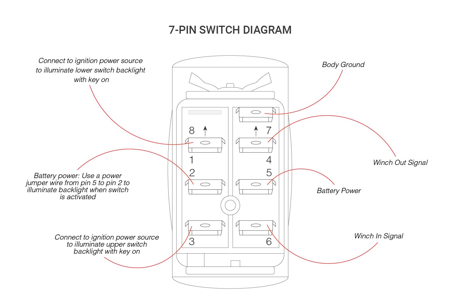
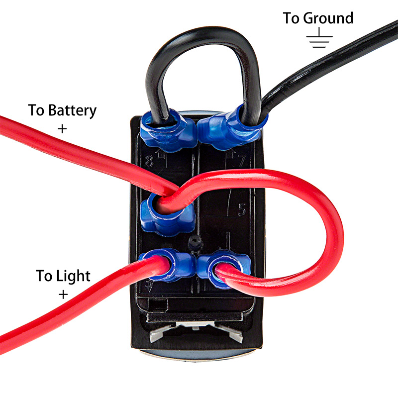
4 pin rocker switch wiring diagram 240v 4 pin rocker switch wiring diagram 4 pin illuminated rocker switch wiring diagram 4 pin led rocker switch wiring diagram every electric structure is made up of various distinct parts. It is off at the bottom on in the center and momentary on at the top.
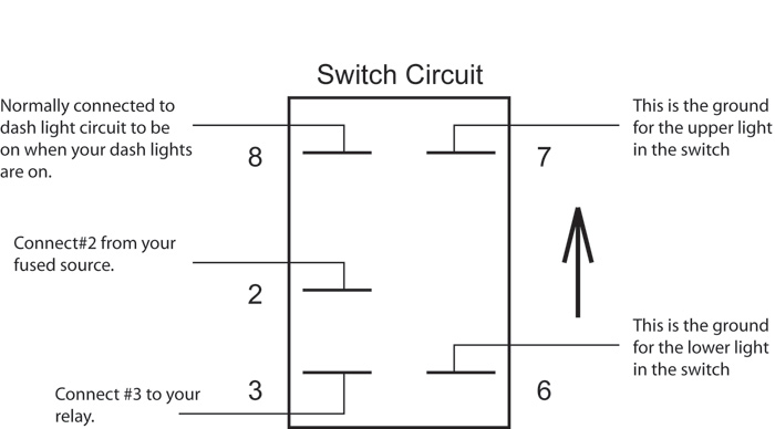
Otrattw Rocker Switch Side X Side World
Rocker switch wiring diagram. 3 backlit bilge rocker switch wiring diagram. Wiring products 810753 views. Learn more about how our awesome backlit switches work here even that one is still pretty straight forward though here are some diagrams that show the single jumper required on the back of the switch. A double pole double throw switch is used for this purpose but you have to wire it up correctly. You might want to review the article on toggle switch wiring before proceeding. Otherwise the structure will not function as it should be.
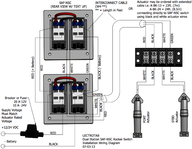
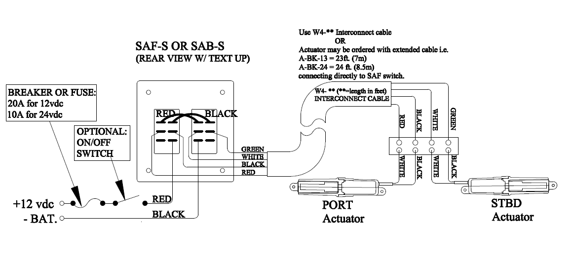
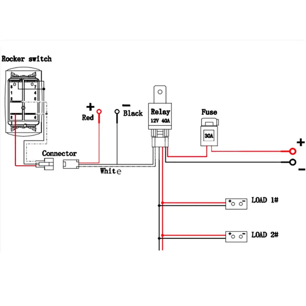
Also relays can be used to switch higher draw accessories to reduce switch load and voltage drop. The diagram below represents the schematic diagram for a spst rocker switch. Many of these switches though are quite flexible thought. For the led rocker switch pay careful attention to the position of your ground power and acc pins follow the diagram below it uses ozniums led round rocker switch with recommended mounting hole diameter of 34 and you should have no problems wiring a led rocker switch. When you need to control a dc motor such as a dc linear actuator you usually need to be able to swap the polarity on the wires going to the motor. A wiring diagram is a streamlined standard pictorial representation of an electrical circuit.
Of the three bilge pump switches the only one thats not extremely simple is the backlit automanual bilge pump switch. Each part should be placed and connected with different parts in specific way. An illuminated rocker switch is like a spst toggle switch with an extra terminal which allows the light to work. The vmdj is a unique dpdt momentary rocker switch. Assortment of 4 pin rocker switch wiring diagram. Wire a dpdt rocker switch for reversing polarity.
With just a few small jumpers our switch selection can be used for a multitude of different functions. Pin 3 is where the switch is either connected to ground or left open. It reveals the components of the circuit as simplified forms and also the power as well as signal connections between the gadgets. Each of our carling rocker switch bodies have the generic wiring diagram loaded into that products own page see photo right. Pin 1 is where the rocker switch receives the input power. The wiring diagram below will demonstrate how to to wire and power this 12v 20amp on on off 3 way carling contura rocker switch.
How to wire a led 3 switch panel with dual usb duration. This rocker is perfect for an engine offrunstart switch. Pin 2 is where the accessory that the switch is going to turn on is connected. Illuminated on off rocker switch with wiring products duration. Led rocker switch wiring diagram.


