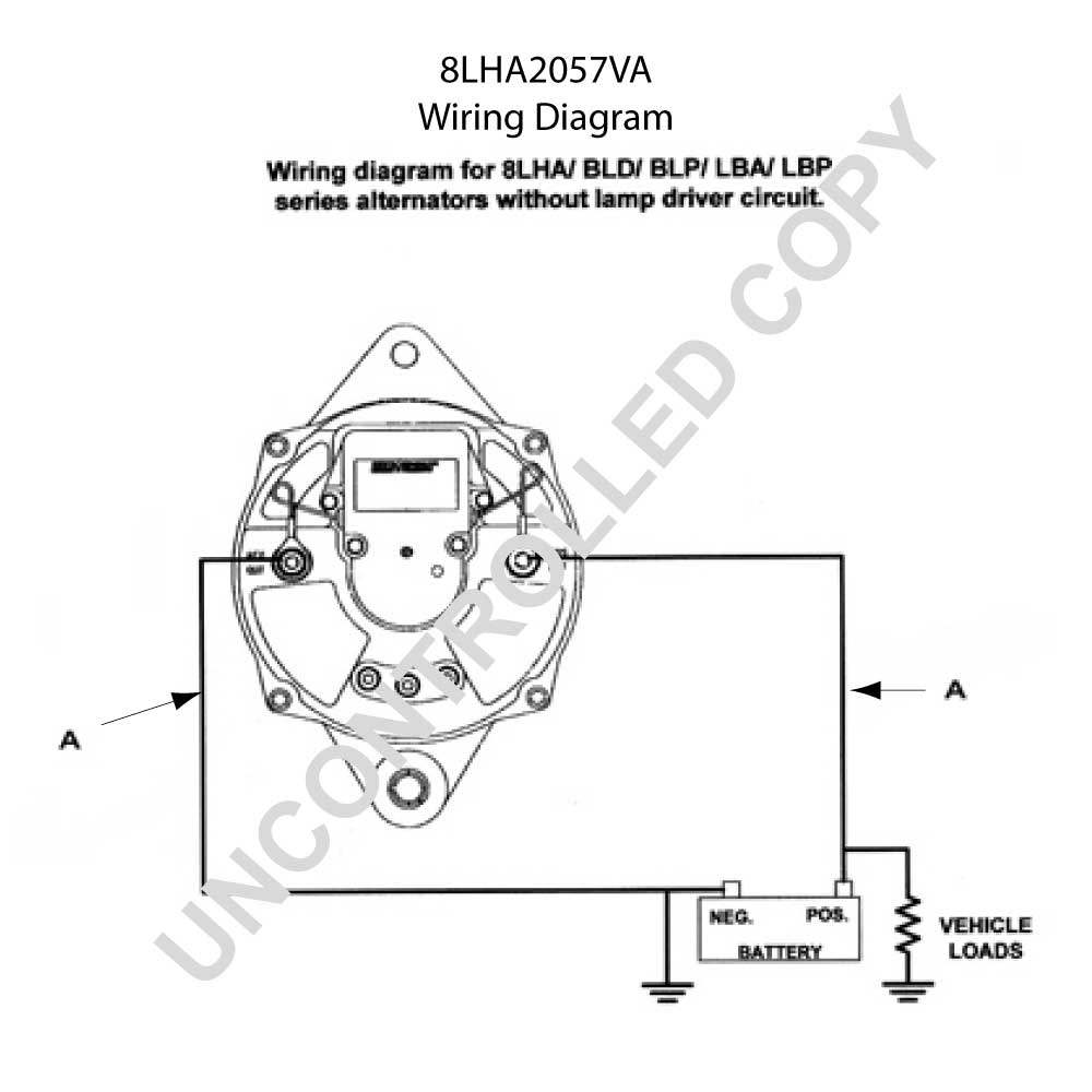
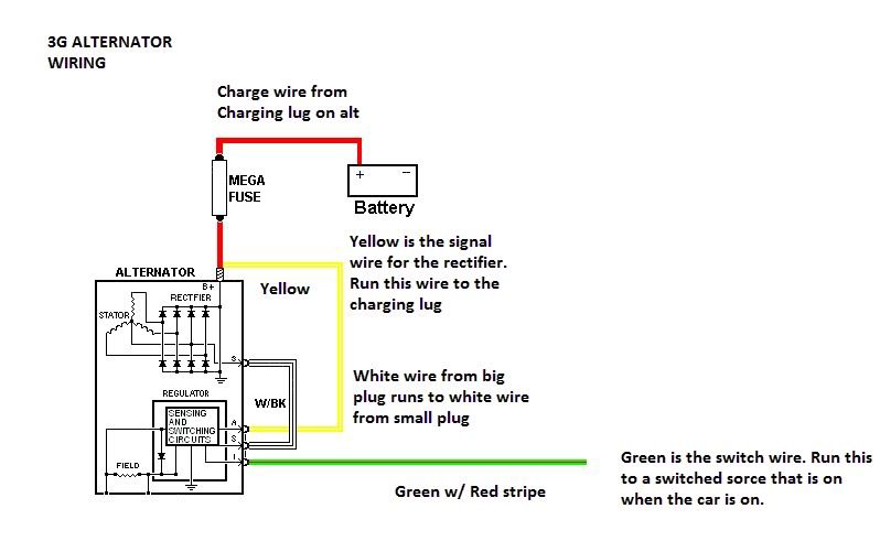
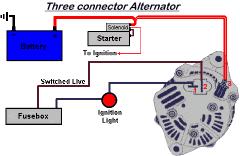
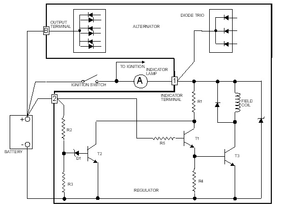
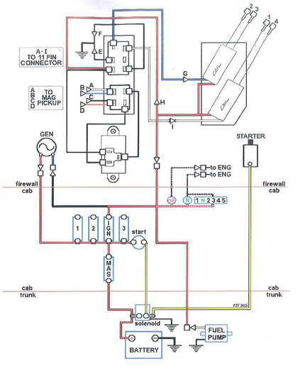
Lightweight aluminum mini 35 amp alternator. Race car alternator wiring diagram wiring diagram is a simplified customary pictorial representation of an electrical circuit.
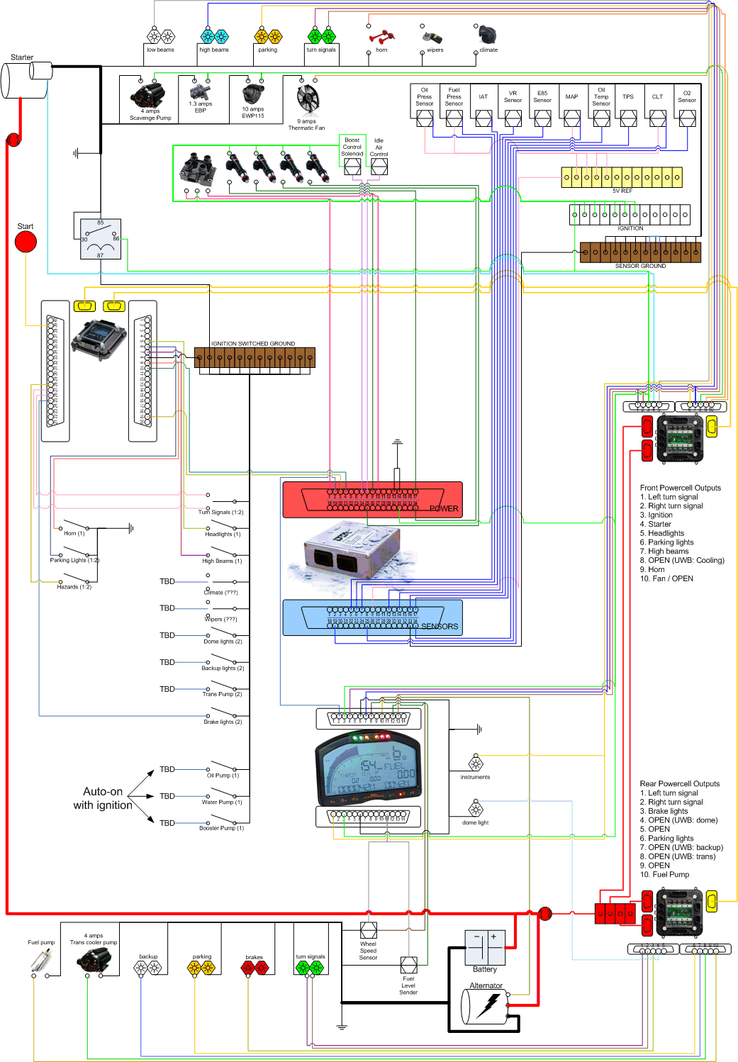
My Race Car Wiring Diagrams Carh 10 Brillenstudio Weichert De
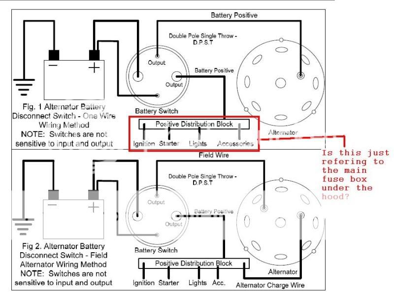
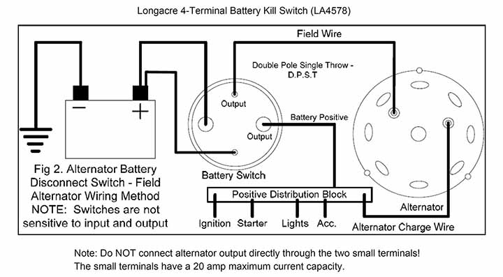
Race car alternator wiring diagram. We know that alternator is used in car or automotive for charging. In this article you will find the alternator function and alternator wiring diagram in a car. A wiring diagram is a simplified traditional pictorial depiction of an electrical circuit. If this is a race car the wire or cable should be run all the way to the battery side of the disconnect switch. This one wire alternator wiring diagram pdf format may be helpful if youre wiring a car up from scratch. This diagram illustrates proper vehicle grounding both to the engine block and also directly back to the battery as your vehicles steel frame has only 20 of the conductivity as.
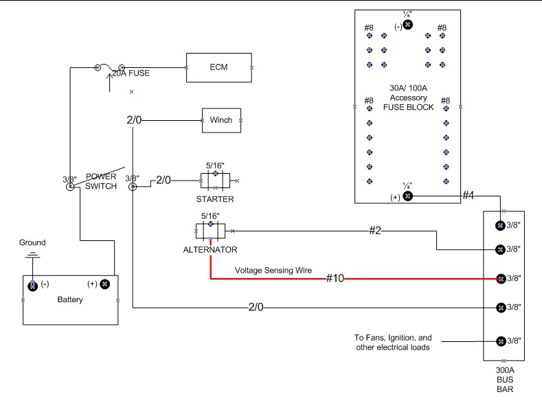
The is done because depending on where the power wire is attached the alternator can power the car even if the battery becomes disconnected from the. Features internal fans and one wire configuration. Collection of denso alternator wiring schematic. This alternator can output a maxiumum of 55 amps at 14 volts for the best performance and reasonable amount of voltage drop you should use a 8 awg cable for a 10 ft or shorter charge wire. It reveals the elements of the circuit as simplified forms and the power and also signal connections in between the tools. Wiring sizes measure from smallest to largest on a numerical scale with zero for the largest size of wire and larger numbers as the wire size decreases.
Charge wire connects from the alternator to the battery through the. Click here to view wiring diagram and output graph. The main function of alternator is to convert mechanical energy into electrical energy in alternating nature. As it creates the alternating current that is why it is called alternator. Race car wiring street stock wiring 101. Rating at 3000 rpm weighs only 56 pounds.
This wiring configuration will excite the alternator to start charging when the engine is running at low rpms. The resistor or directly to the key switch itself switched side. This means that the alternator and the battery would be on one side of the switch and the circuits would be on the other side. It shows the components of the circuit as simplified shapes and the aptitude and signal contacts along with the devices.


