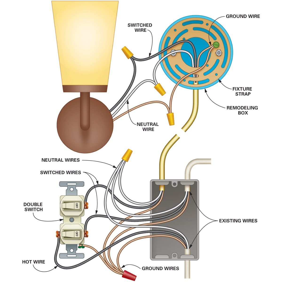
Motion sensor light wiring diagram wiring diagram for outdoor flood light awesome new motion sensor light wiring diagram australia inspiration best. Depending on this information a separate dedicated circuit may not be necessary or required.

Low Voltage System Layout
Outdoor light wiring diagram. Free wiring diagram menu. You can power your garden lights from a spur off a ring circuit via a 5 amp fused connection unit. Cover with a plastic wire nut. September 3 2018 february 28 2019 by larry a. Connect the black wire from the motion sensor to the black wire that is coming from the power supply circuit breaker or fuse. Ensure all connections are tight.
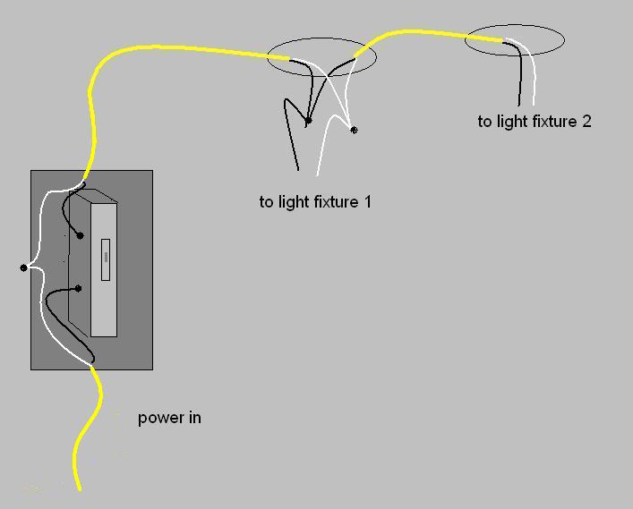
Twist the two white wires together in the same fashion. One outside light on two. Type uf cable is the most commonly used nonmetallic cable for residential outdoor wiring runs. It may be necessary to extend the live feed wire and common wire using a 5 amp terminal block. The rules for outdoor lighting are principally about using fixtures that are rated for use in damp or wet locations. Garden lighting and outdoor electrics safe installation.
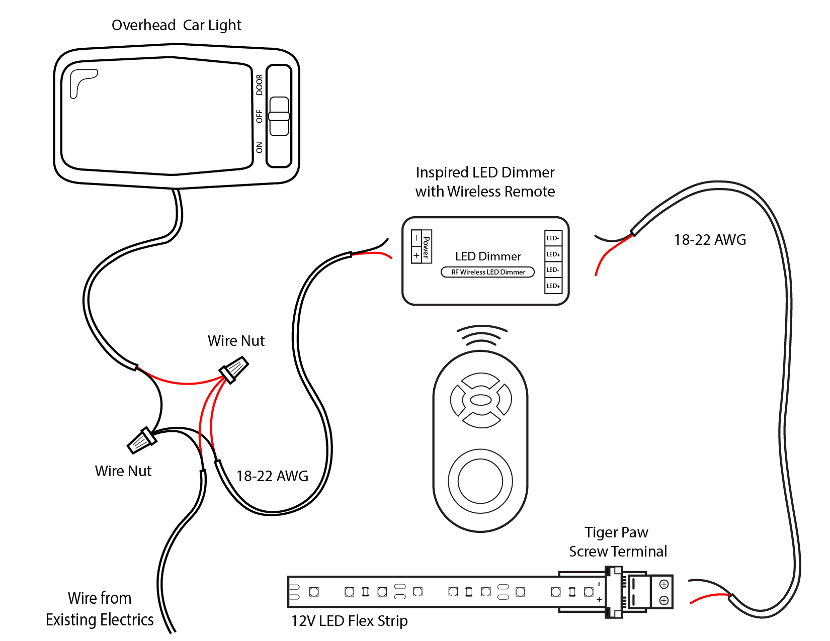
Wiring diagram for outdoor motion detector light 2017 motion sensor wiring diagram for outdoor flood light. It reveals the components of the circuit as streamlined forms as well as the power and signal. How to install wiring for outdoor lighting. Click on the image to enlarge and then save it to your computer by right clicking on the image. Once outdoors you should supply your lights via 15mm² three core steel wire armoured cable swa. Collection of motion sensor light wiring diagram.
Wiring in pvc conduit must have at least 18 inches of cover. Twist the red insulated bare copper wire from the motion sensor together with the black wire from the light fixture. Make a good electrical connection using the pliers. From inside and ensuring the lighting circuit is switched off prepare the new wiring to be partnered to the existing wire. Landscape lighting wiring diagram name. Uf cable can be direct buried without conduit with a minimum of 24 inches of earth cover.
Wiring for outside fixture wiring. Advice on wiring garden lights and outdoor lighting cables and regulations. With the switch still away from the wall reconnect the electrical supply and use the switch taking care not to touch any metallic. Wiring buried inside rigid metal rmc or intermediate metal imc conduit must have at least 6 inches of earth cover. The method used to install wiring will depend on the location and the type of outside lights and how many will actually be installed. Adding the live wire to the switch and the new common wire which may be taped or connected by other means.
Landscape lighting wiring diagram line voltage landscape lights lovely low voltage outdoor lighting wiring. Make sure that you only fit weatherproof lights that are suitable for outdoor use and that your circuit is rcd protected. Finally connect the bare grounding copper wire back to the metal. Collection of low voltage outdoor lighting wiring diagram. Low voltage outdoor lighting wiring diagram. Cover the bare copper wires with a wire nut.
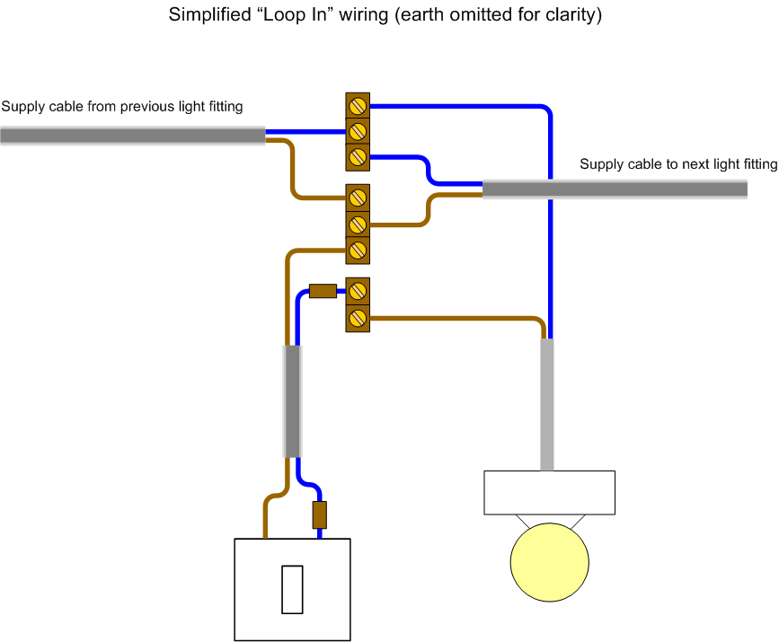
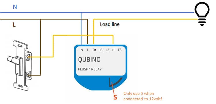
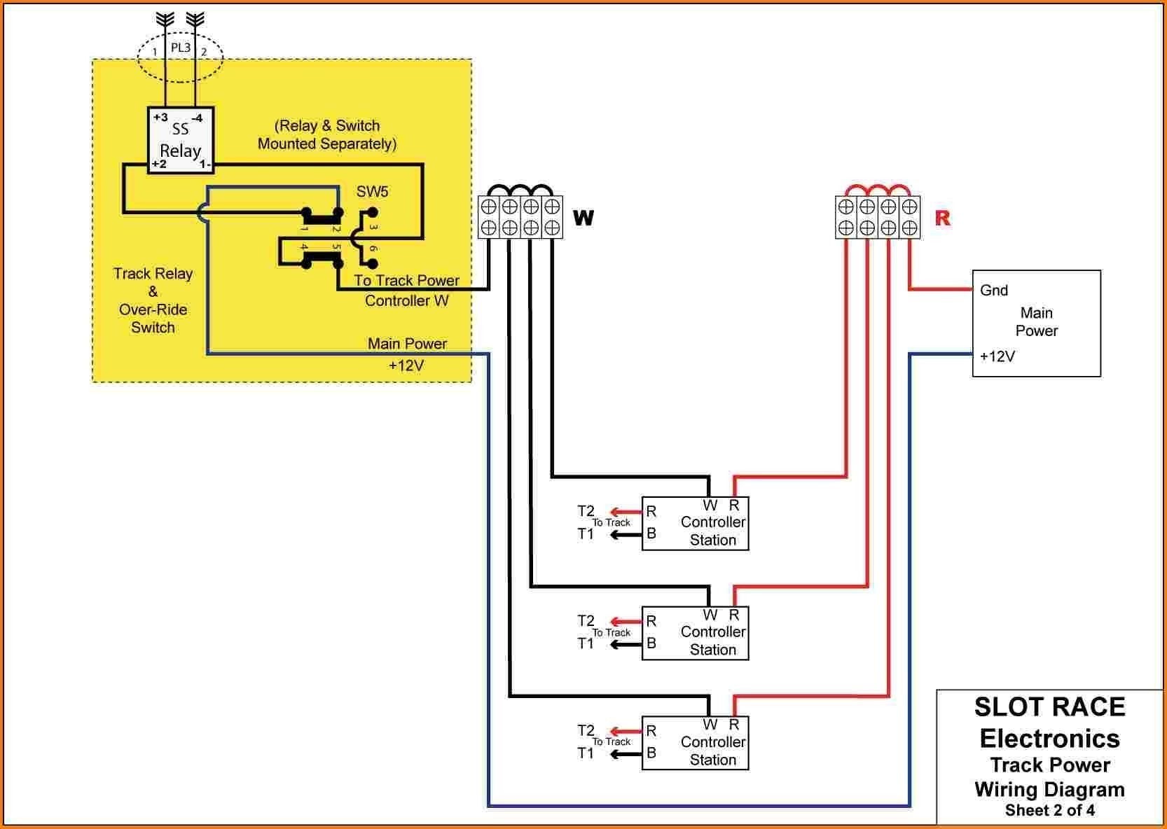
A wiring diagram is a simplified standard pictorial depiction of an electric circuit. Outside lights may be controlled by motion detectors and photo cells switched from one or more locations or may be controlled by a simple home automation system. Wiring diagram for outdoor lighting save fabulous how to do low.

