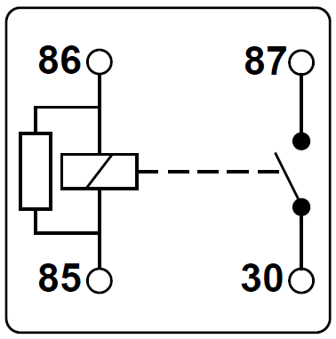
Visa versa normally open pole com is attached with coil when the coil of relay is magnetized. Switch connections of relay are mostly named as pole com normally closenc normally open nopole and com is equal to common normally closed and normally open is always connected with the moving part of the switch.

Relays And Actuators Openlabpro Com
Normally closed relay diagram. Relay logic the com common connection of a relay is the part of the relay that moves. The basic starter kill relay diagram shown below breaks continuity of the wire from the ignition switch to the starter motor or in some cases ie. Starter kill normally closed relay wiring diagram. Normally closed relays are used to keep ac unit blowers running even after the air compressor shuts off allowing the system to continue generating residual cool air without running the compressor. In figure 1 no dc voltage is applied to points a and b therefore no current flows through the coil of the relay the contact stays in the close position and the fan will be switched on because it is connected to the 220v. If any students ask what spdt means refer.
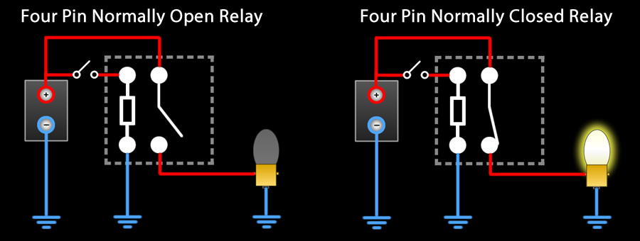
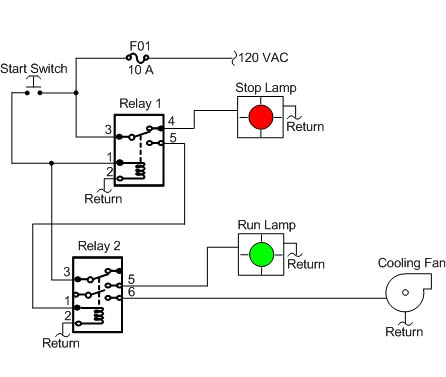
Normally close pole com is attached with coil when the coil of relay is nu magnetized. Normally closed relay applications. In order for this circuit to function as specified the green light bulb must receive power through the relays normally open contact and the red light bulb through the relays normally closed contact. Relays are switches that open and close circuits electromechanically or electronically. Video presentation of how the normally closed spst relay works. Some example is show in below.
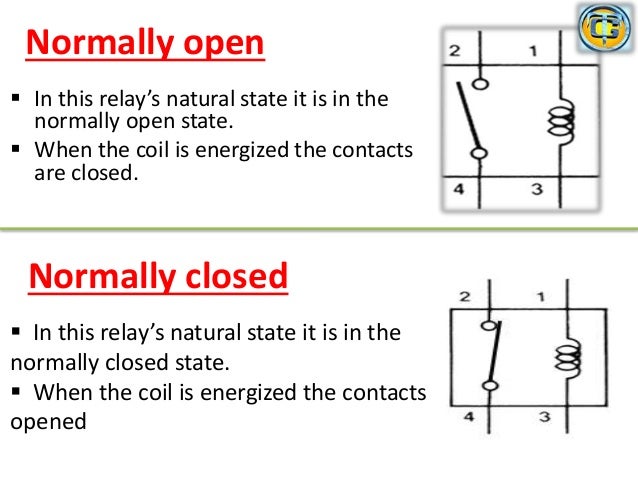
As relay diagrams show when a relay contact is normally open no there is an open contact when the relay is not energized. It takes a relatively small amount of power to turn on a relay but the relay can control something that draws much more power. Connecting additional devices to the remote turn on wire. In these systems normally closed relays act as safety features stopping power to the gas valve in the event of a malfunction. For instance the following diagram shows a normally open pushbutton switch controlling a lamp on a 120 volt ac circuit the hot and neutral poles of the ac power source labeled l1 and l2 respectively. The coil that controls the relay may only need a few watts to pull the.
This is the most commonly used application for disabling the starter. A relay is used to control the air conditioner in your home. Check out the picture below to better understand how this process takes place. Constant to momentary. Gas valve control systems. The no normally open connection of the relay is not connected until the relay turns on.
Here are just a few systems that require normally closed relays. The ac unit probably runs off of 220vac at around 30a. When a relay is off the common is connected to the nc normally closed. Diagrams will show how multiple relays one relay or another or just one relay can control your device. In figure 2 we apply a dc voltage lets say 12v to the coil points a and. All examples shown are for spdt single pole double throw relays which includes any of the 5 10 or 20 amp relays on this site.
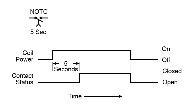
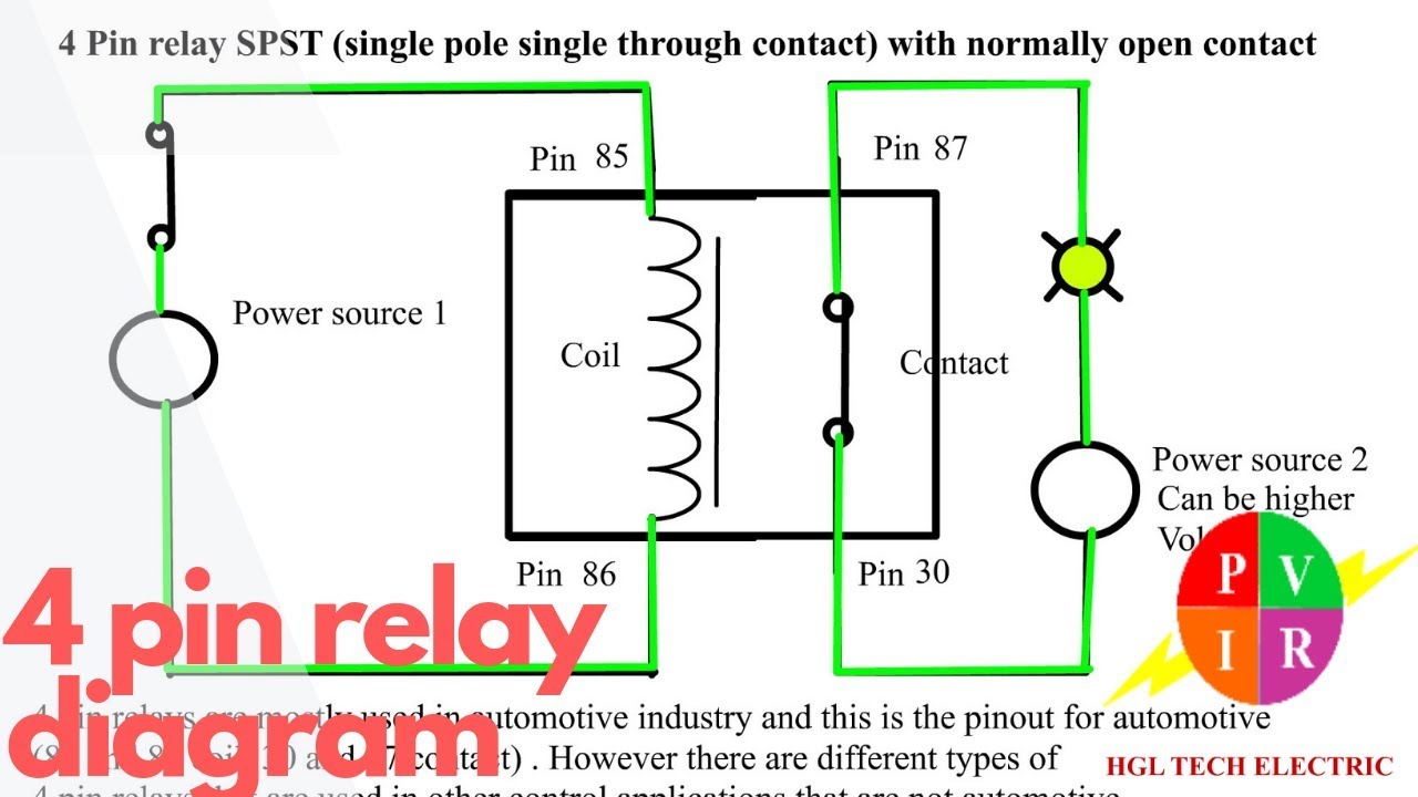
Normally closed single pole single throw spst relay. Relays control one electrical circuit by opening and closing contacts in another circuit. A relay is an electrical switch that uses an electromagnet to move the switch from the off to on position instead of a person moving the switch. Complete the schematic diagram for a spdt relay circuit that energizes the green light bulb only when the pushbutton switch is pressed and energizes the red light bulb only when the pushbutton switch is released. Relay diagrams quick reference last updated. Ford to another relay when the alarm is armed and the ignition is turned on.
When a relay contact is normally closed.
Gallery of Normally Closed Relay Diagram