One side of the gfci connected to the ground neutral wire as shown white in the diagram and another side to the high potential hot wire shown as black in the diagram shows as in black color. The neutral wire from the circuit is shared by both sets.
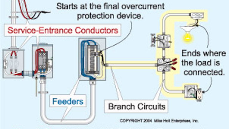
Branch Circuits Part One Ec Amp M
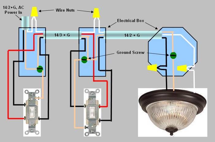
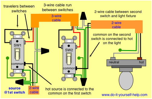
How to wire a 3 way switch with multiple outlets. Do not try to wire the 3 way through the outlets it would get a bit complicated. When nothing is hooked up there is power in the 2 wire plus ground cable on the upstairs switch. Finally twist the ground wires together and connect one of them to the green ground terminal. With the increasing number of electrical devices being used in the home today extending existing wall outlet circuits or installing new. The above diagram shows the gfci wiring to multiple outlet as in white while the pictures are same. Just replace the light fixtures with outlets.
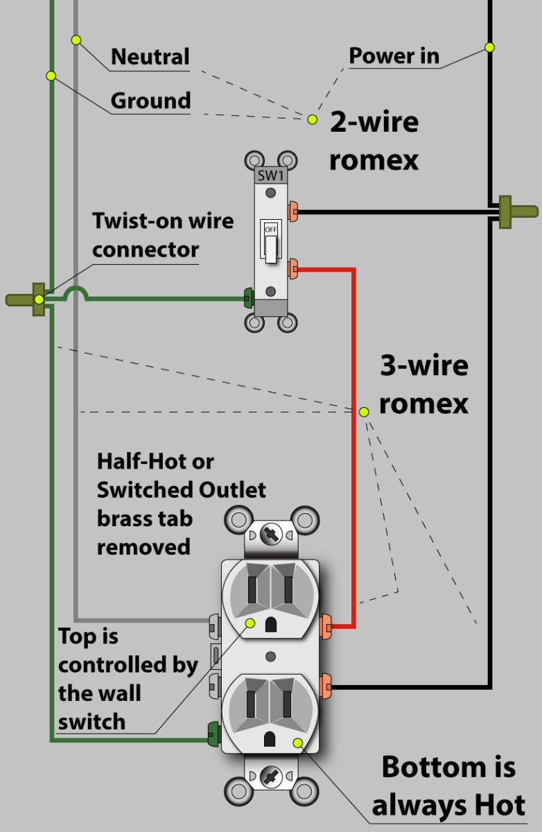
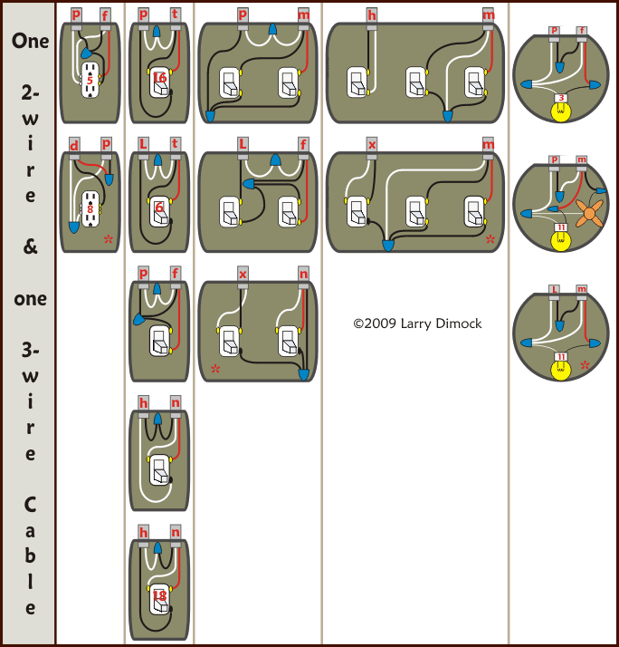
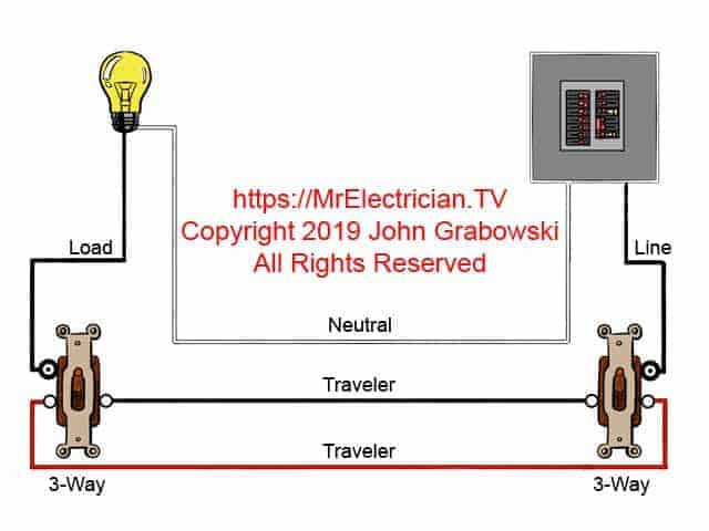
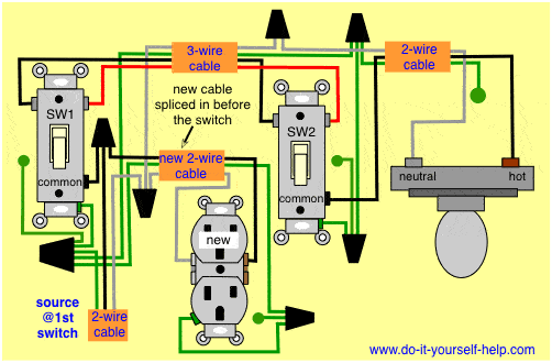
Here 3 wire cable is run from a double pole circuit breaker providing an independent 120 volts to two sets of multiple outlets. A three way switch diagram that is used for light fixtures can be easily used for outlets. There is only the single 3 wire plus ground in the downstairs switch box and only two 2 wire plus ground cables at the fixture. How to install a wall outlet in a three way switch circuit. Be sure to provide gfci protection as required. The hot source at the outlet is spliced to the black wire running to the switch and the hot wires running to the other outlets in the circuit.
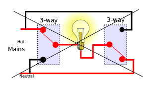
Both travelers red and black must be continuous from the first to the second switch. Then from the second switch you would connect the non traveler now the switched wire to each outlet. This wiring is commonly used in a 20 amp kitchen circuit where two appliance feeds are needed such as for a refrigerator and a microwave in the same location. One of the switches will have its common point black screw connected to the outlets. The two switches appear to be connected by a 3 wire plus ground cable. The best way to wire 3 way switches is too run a 3 conductor wire between the two 3 way switches not through the outlet.
Connect the outgoing hot wire black to the bottom brass terminal and the outgoing neutral wire white to the bottom chrome terminal. Fully explained wiring instructions and wiring diagrams can be found here in the 3 way switch area here in this website. Just click the 3 way switch diagram link. The switch takes the hot from the middle receptacle here and 3 wire cable runs from there to the new switch location. The socket of gfci indicates as one pair in each for protection of any circumstances because of any switching impulse withstand voltage or any switching impulse withstand voltage while the timing for.
