Simple dc motor forward and reverse control circuit httpsyoutubetsbpnxxspvg share comment subscribe like. In the diagram i connect the incoming three phase supply l1 l2 l3 to the mccb circuit breaker molded case circuit breaker.

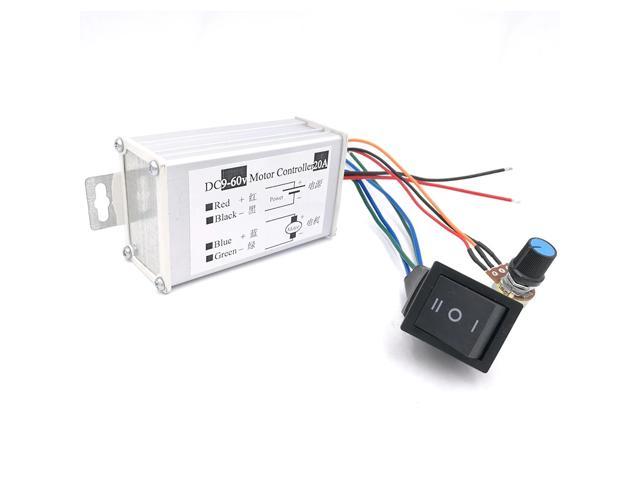
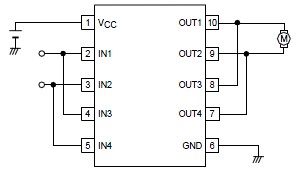
Dc Motor Driver Module 5v 12v 24v 20a Forward Reverse Controller Self Locking Wide Voltage Drive Module Motor Limit Control
Dc motor reverse forward circuit. Again this is how cars power drills and many other equipment work. In this video i have made a dc motor reverse forward control circuit using very common components. This circuit can be used to control direction of many dc motors such as 3v motor 5v or 12v motors. Forward and reverse direction of dc motor by changing the supply polarity in field winding or filed supply. Have a dc motor wired to an onoff switch and 2 microswitches. The dc motor controls a mechanism that moves the switch to the other direction but in the middle of moving the switch the motor stops in the middle position since there is a temporary open circuit.
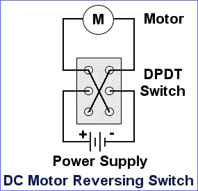
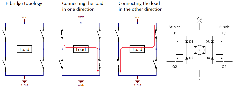
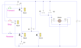
Here i showed the forward reverse wiring diagram. A switch is used to turn dc direct current motor forward and reverse. In the above forward reverse dc motor using relay double pole double throw relay wiring diagram. Each switch will reverse the direction of the motor so one switch tells the motor to go forward the other tells the motor to go reverse. Below is the bidirectional dc motor circuit which allows forward and reverse motion with the flip of a switch. Dc motor reversing circuit.
Field terminal consist of f1 and f2. When the switch is thrown down the motor spins in the opposite direction. So here is what i am trying to do. And the second switch which is connected in the way of positive wire is used for switch onoff the motor. Also read dpdt relay wiring diagram. We use 2 magnetic contactors as forward reverse switch.
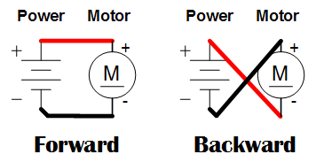
The dc motor is connected to the supply through dpdt double pole double through switch by changing the switch position we can get forward and reverse rotation from the dc motor because this switch interchanges power supply polarity applied to the dc motor. When the switch is up the motor spins in the forward direction. My goal is to have a track where the motor will pull a platform in one direction then when it gets to the end of the track it will hit the switch and then cause it to go the other way down. Circuit for a dc motor with 2 microswitches reversing direction. For three phase motor forward reverse control circuit. Normally in forward direction the dc supply will be given such as f1 positive and f2 negative to change the direction the polarity should be f1 negative and f2 positive.
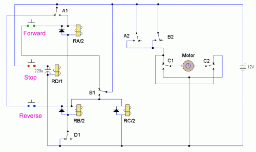
And the motor cannot be switched from forward to reverse unless the stop switch is pressed first. Except for the back emf diodes across the relay coils this circuit is identical in function to the example shown on the. Two one way switches used. There is no relay involved.
