The sensor blue wire is not used and should be capped off with a wire nut. For most updates and latest information about awesome cooper light switch wiring diagram graphics please kindly follow us on tweets path instagram and google plus or you mark this page on bookmark area we attempt to provide you with up grade periodically with fresh and new pics love your exploring and find the best for you.
Cooper Gfci Schematic Wiring Diagram H1 Wiring Diagram
Cooper light switch wiring diagram. Neutral 120277v lighting branch circut neutral 120v receptacle branch circut sp r 20 120 receptacle switchpack 24v ceiling occupancy sensor controlled receptacle dimmer switch a 0 10v dimmer supported wallbox dimmers are cooper divine. A switch provides a mechanical method for opening and closing a circuit. Wiring is done in the same method as any other switch. Cooper light switch wiring diagram tr274 schematics wiring diagram cooper lighting wiring diagram wiring diagrams best 3 way light switches diagram 3 way wiring diagram for led light cooper double switch wiring diagram wiring diagram libraries how to wire a light switch smartthings mini wiring diagrams wiring diagram site. Cooper wiring diagram single pole light switch explained bination double leviton three way dimmer switch wiring diagram fresh cooper 3 for with wiring diagram cooper 3 way switch refrence. When the dimmer switch is off both lights and receptacles are switched off.
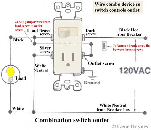
The sensor red wire will connect to the wire which goes to the light fixture. The 15 amp 120 volt cooper light switch 1301 7w is the standard style of switch used in modern construction. The sensor black wire will connect to the hot wire black in the wall box. They are typically connected using 143 gauge electrical wire. For single pole applications wire the sensor switch according to wiring diagram 1 using the wire nuts provided.


:max_bytes(150000):strip_icc()/anatomy-of-a-three-way-switch-1152436-final-ddc55160d5cb47929688406fda972301.png)


