Your rv has two separate electrical systems. Types of rv electricity there are 2 main types of sources of rv electricity within your rv 12 volt dc and 120 volt ac same as 110 volt just like your stick brick for our purposes.

Todd S Teardrop Blog Electrical System Beginning Stages
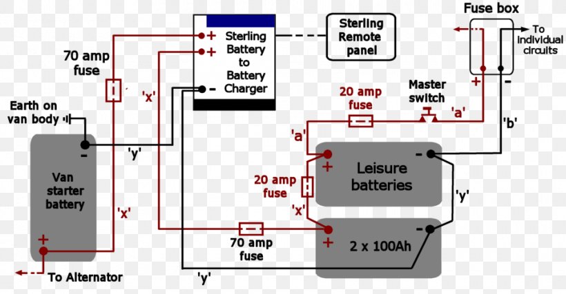
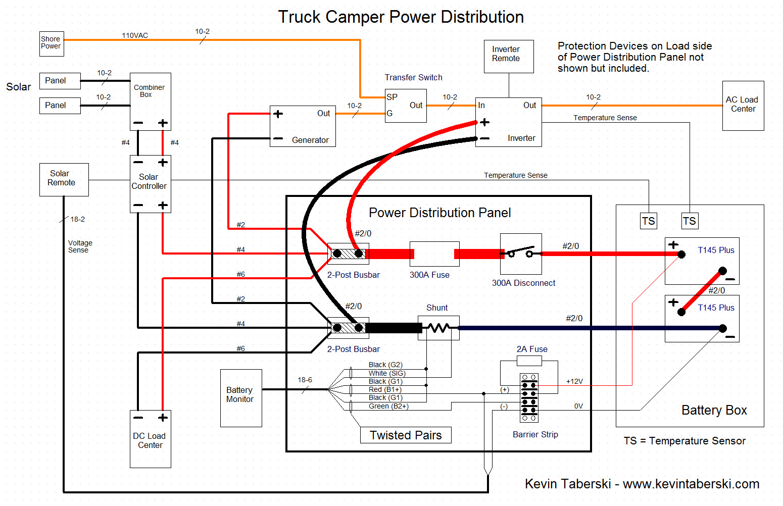
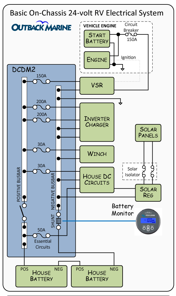
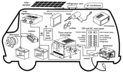
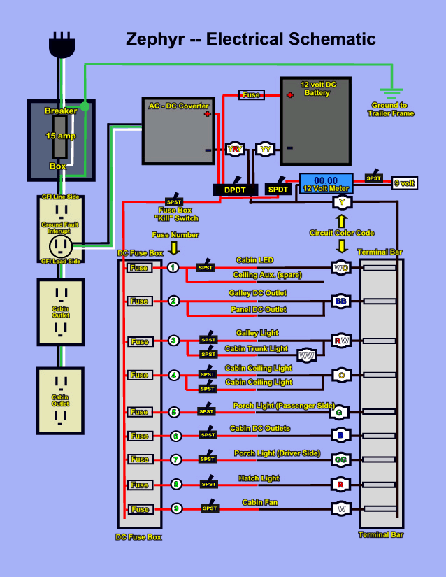
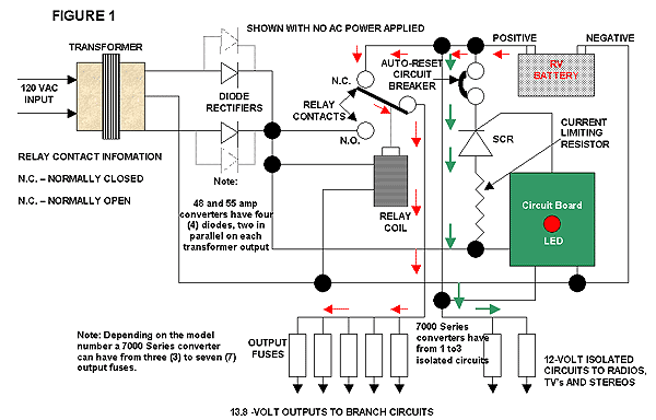
Camper electrical system diagram. Rv electrical diagram wiring schematic understanding you campers electrical wiring can be very confusing. The most popular option today is a 7 pin flat connector but you can also use a 12 pin flat which provides 5 additional heavy duty pins and is compatible with the 7 pin flat. Use the rv electrical diagram we made below to get an understanding of what powers what and to learn how an rv electrical system works. Normally when you plug your rv into shore power the current flows to your 110v ac breaker panel where it is then dispersed to your electrical outlets for plugging in small appliances 110v lights or. Wiring diagram od rv park 1995 fleetwood southwind rv wiring diagram a newbie s overview of circuit diagrams a very first appearance at a circuit representation may be complicated but if you could check out a train map you can review schematics. Free wiring diagram and tutorial inside.
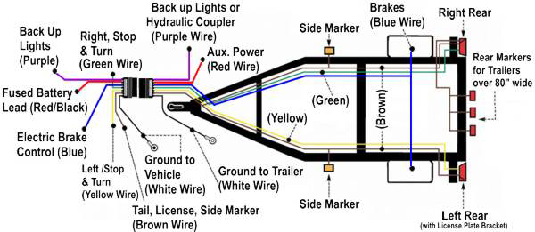
All trailers require basic 7 core wiring for the tail light clusters and electric brakes. One rv two electrical systems. In this diagram youll see that this is the most common rv electrical set up and the basic type most often installed by manufacturers. Now most electrical experts will agree that the converter that comes from the factory in most rvs while functional is not the best method for charging your house batteries. The 12 volt system is powered by a battery or in some cases multiple batteries and it powers things such as the start up on your water heater furnace and refrigerator plus most of the lights in your rvs living space your water pump your carbon. Assuming the batteries are 50 efficient id need to fit 160ah batteries.
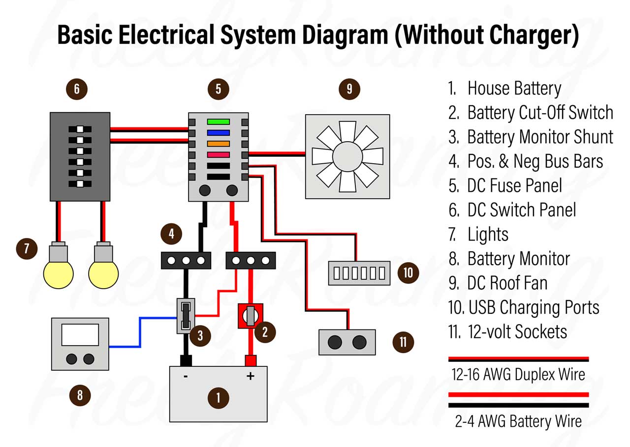
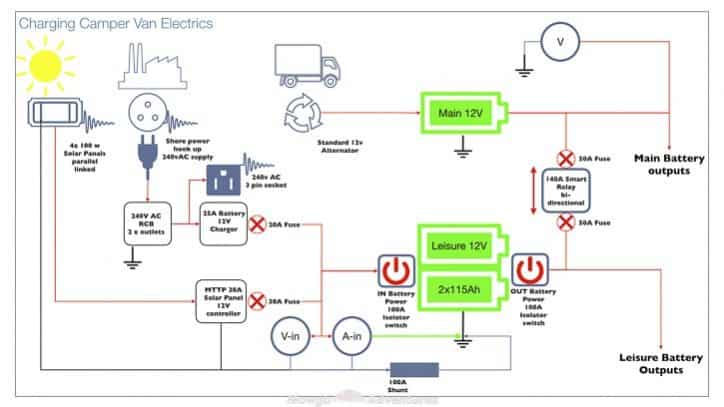
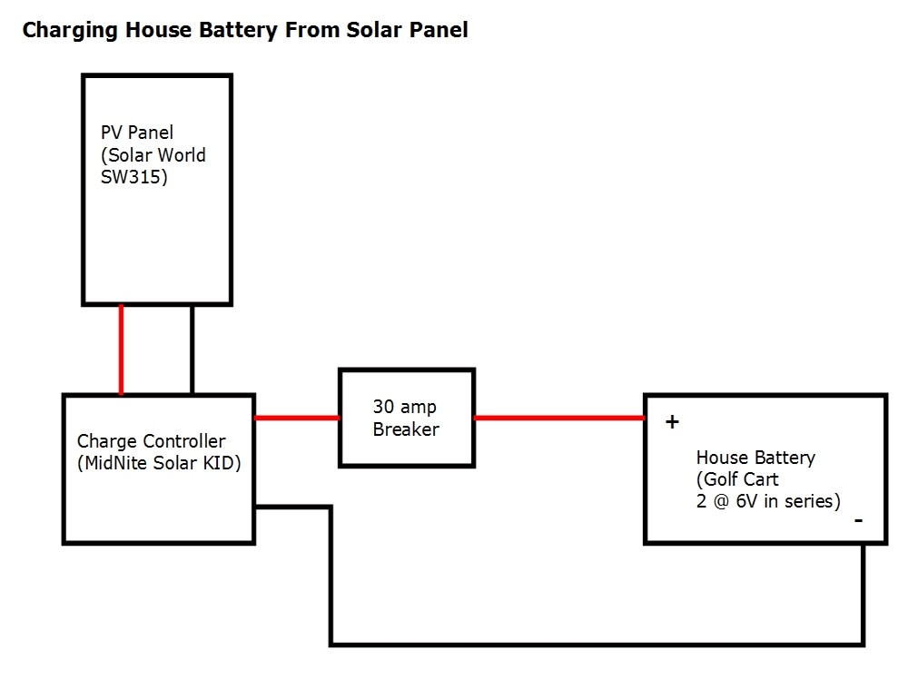
See this wiring diagram for the correct plug and socket wiring for both round and flat connectors. The diagram above outlines in the most simplistic terms my camper van electrical design. The diagram below shows a typical rv electrical system set up with a converter. Below is a rv electric wiring diagram or schematic including the converter and inverter for a generic rv. Complete guide on designing and installing your own diy electrical system in a camper van conversion. Rvs use both ac alternating current and dc direct current to power the components of your electrical system.
The 12 volt dc system runs the electrical components of the engine and battery of your ride while the 120 volt ac system runs all the typical appliances and power outlets found on most rvs. In fact that is probably an understatement. A 12 volt dc electrical system and a 120 volt ac system. Using the formula explained here i calculated id need about 80 amp hours ah per day including contingency.
