My fan has four speeds off slow medium and fast. Update october 13 2008.

Four Wire Fan Diagram Wiring Diagram
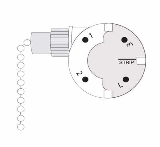
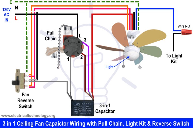
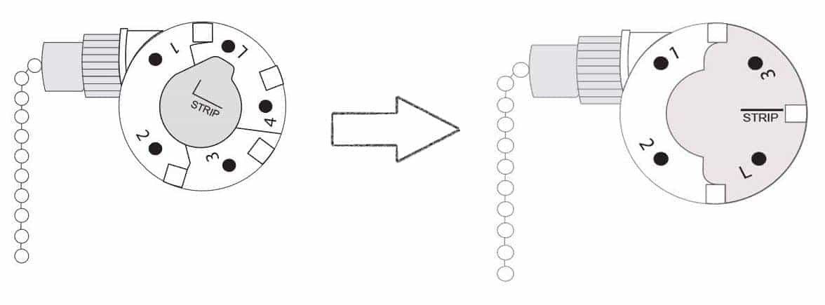
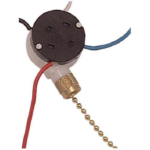
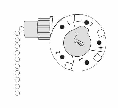
4 wire fan switch color code. Fan uses control ic bd6709nfs from rohm company. Signal description is included as well. I purchased a 3 speed 4 wire fan switch model number ze 268s6 and i am trying to figure out where to insert the color wires. This color of wire is used to transfer power to switches and outlets in all types of circuits. Black wire in terminal 3 and terminal number l 1 2 3 is in counterclockwise order. The old zing ear switch i am replacing is a shine top ls 102 6a125vac 3a250vac e218558.
L orange wire 2 purple wire. 4 wire ceiling fan switch wiring diagram 4 wire ceiling fan switch wiring diagram throughout carlplant best. Connect the green wire to your household ground wire copperbare wire. Also black wires are often used as switch legs in circuits which is the connection linking a switch to the electrical load. What the color of an electrical wire means black electrical wires. Consider all black wires to be live at all times.
Made of silicon electrical steel sheets and winded with 9999 pure enameled copper wire fan stator is the core technology in manufacturing electric fans. Here gnd is 0v and 12v is the positive supply for the fan. Intel developed connection standards for 4 wire fans. Shine top ls 102 fan switch. Black wire in terminal 3 and terminal number l 1 2 3 is in counterclockwise order. Following is the connector pin out and wire color code of a typical 4 wire fan.
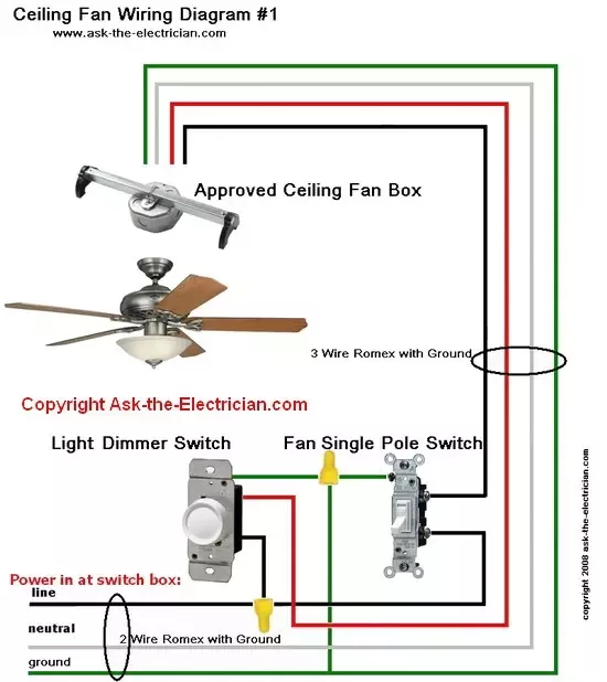
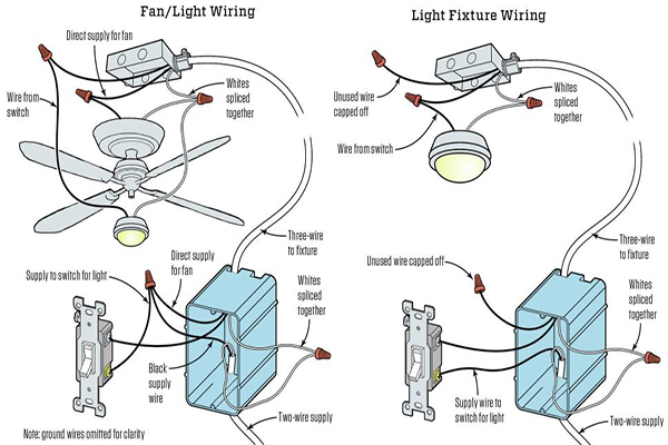
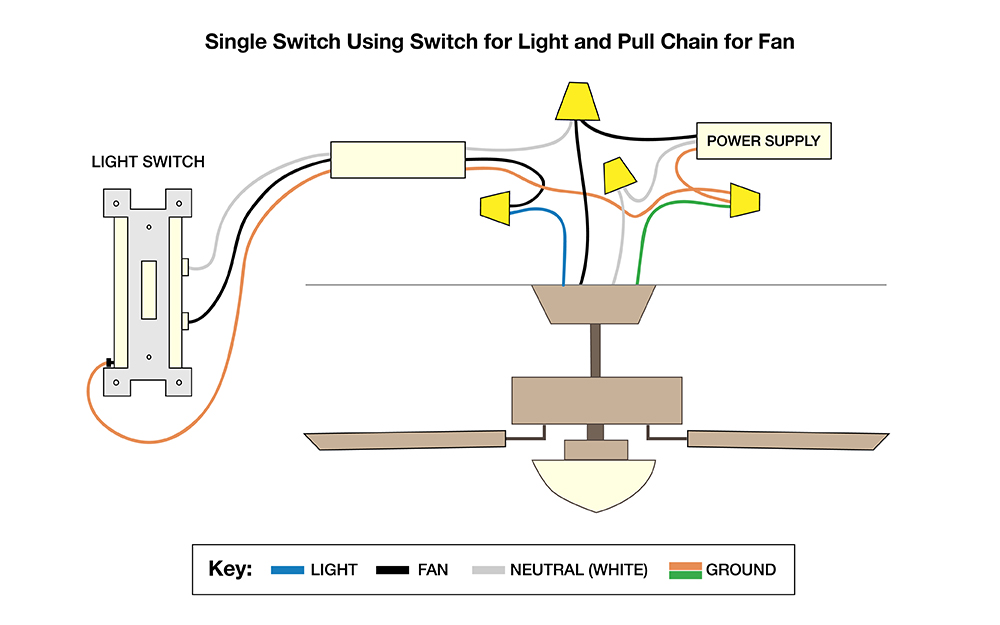
Wu pin ljy 280a 4 hole fan switch. 4 hole switch with black wire in terminal 3 defond 4 hole fan switch. Variety of 4 wire ceiling fan switch wiring diagram. Santa 4 hole fan switch. In order for the light to be controlled by its own switch the wiring between the switch and the fan unit needs a fourth wire a red wire to carry power to the light kit. Click on the image to enlarge and then save it to your computer by right clicking on the image.
Vice versa it is possible to use old 3 wire fan on new board with 4 wire header but with limited possibility of pwm control depending on board logic. Black wire in terminal 3 and terminal number l 1 2 3 is in counterclockwise order. Teoretically is possible to use 4 wire fan like 3 wire on the board with 3 wire connector. The current wiring for the old switch are as follows.
:max_bytes(150000):strip_icc()/ElectricalWiring_FINAL2-5c01dc0546e0fb0001f4d760.png)


