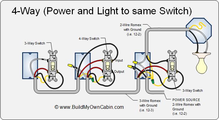
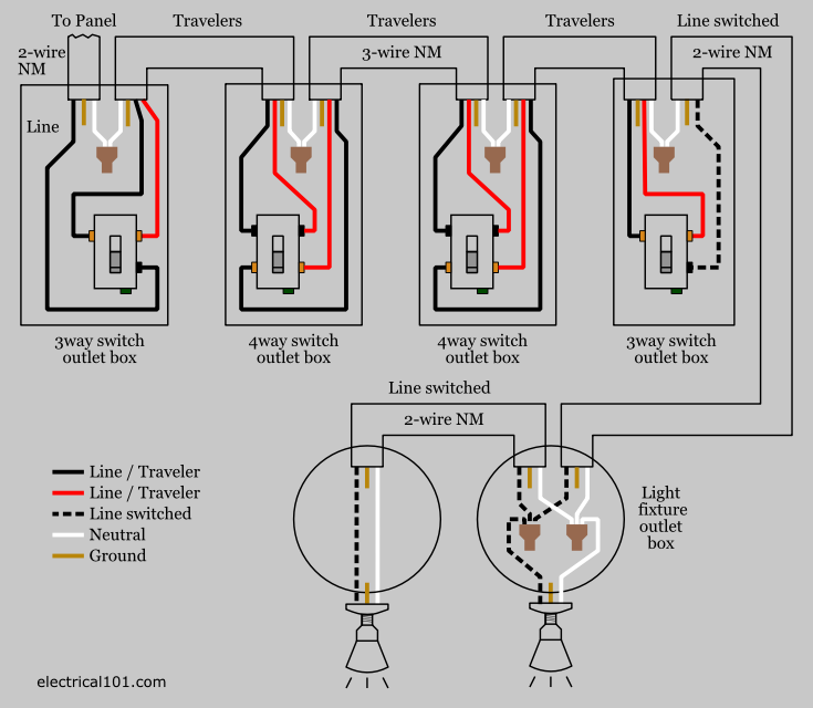
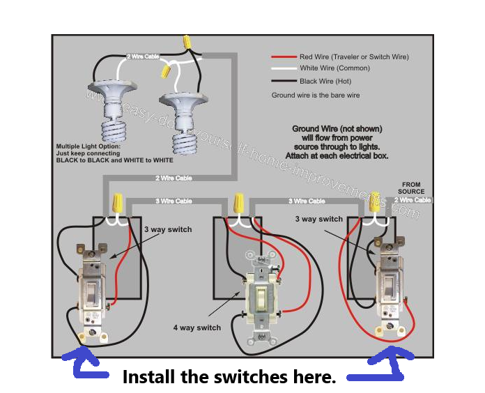
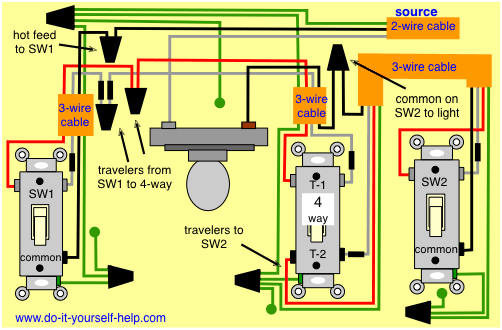
In the diagrams below the first switch 3 way common terminal connects to line voltage. 4 way switches have four terminals each with two pairs of travelers one set usually black and one set usually brass color.

Power Fixture Feed 2nd 4 Way Switch Electrical Wiring Done Right
4 way switch power at light. A 4 way switch as shown in figure 1 is used to turn a light fixture offand onfrom three or more locations. Starting with safety and understanding 1. 4 way light switch with power feed via the light. If the device is still. 4 way switches can be quickly. 3 way switch wiring diagram part 2.
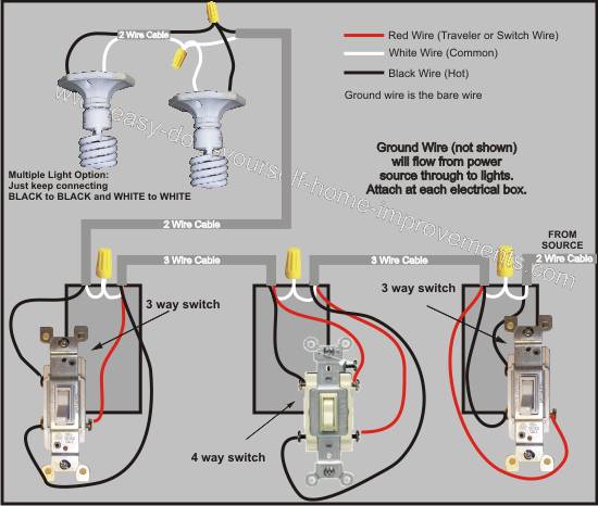
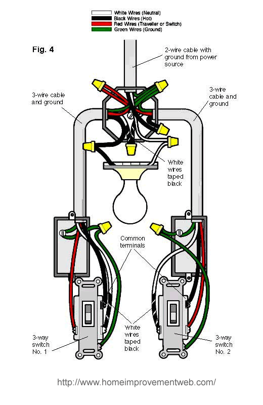
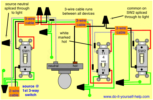
Do you need a 3 way switch wiring diagram. Wiring a 4 way switch to a light fixture. The hot source is connected to the common terminal on the first switch sw1 and the hot terminal on the light fixture is spliced through all the light fixture to the common terminal of the last switch. A four switch configuration will have two 3 way switches one on each end and two 4 way switches in the middle. This 4 way switch diagram 2 shows the power source starting at the fixture. If you have a requirement to turns lights on and off from more than 2 location it requires the use of 3 way and 4 way switches.
Power from light fixture to light switch. I have a few of the most common ways in wiring a 4 way switch to help you with your basic home wiring projects. A 4 way switch wiring diagram is the clearest and easiest way to wire that pesky 4 way switch. Turn off electric power. Usually when a 3 way or 4 way switch fails lights can be toggled on and off on all but one switch. This circuit diagram shows wiring for a 4 way circuit with the power source at the light fixture and the switches following.
Turn on the light or device being controlled by the 3 way switches if you already have them. In this 4 way light circuit the power source is via the first switch sw1. Follow these steps to find which 3 or 4 way switch is bad. You must purchase switches labeled as 4 way switches rather than 3 way or normal light switches. Locate a bad 4 way switch. A three wire cable runs between all the switches connecting the travelers.
The white wire of the cable going to the switch is attached to the black line in the fixture box using a wirenut. The white wire becomes the energized switch leg as indicated by using black or red electrical tape. Any switch that toggles the lights on and off is probably working properly. A two wire cable c2 is run from the light to the first switch sw1 and a 3 wire cable runs between all the switches. The hot connects to the common on that switch and the neutral is spliced through all the switch boxes to the neutral terminal of the light. Toggle each switch until the light come on.
Four way switches are used to control power to a light from three or more different locations. Return to location you plan to wire to verify that there is no electric flow to that device.


