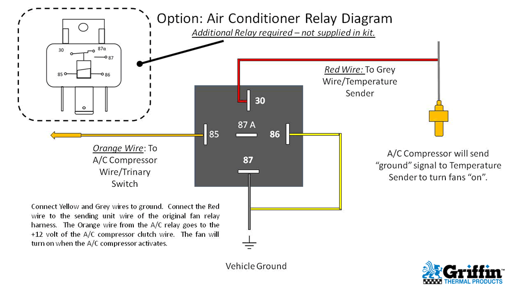
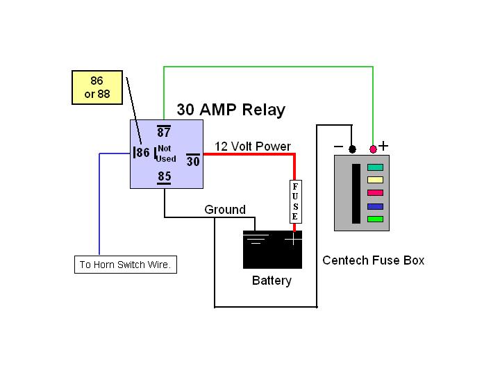
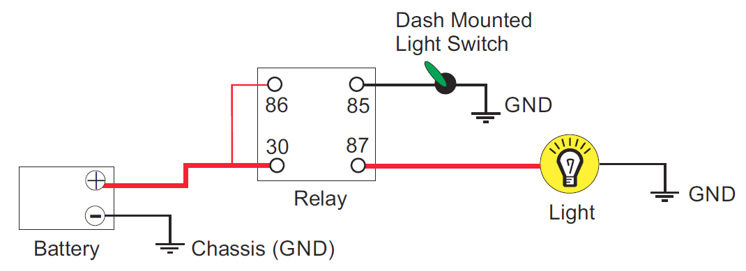
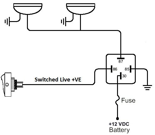
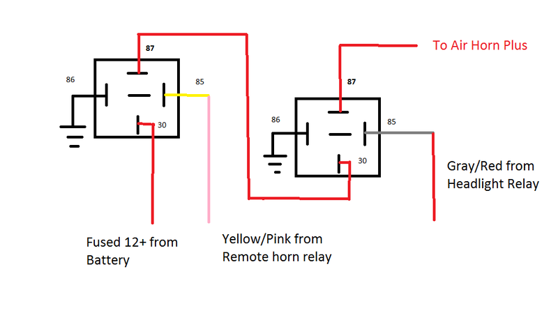
4 pin relay wiring diagram horn wiring diagram is a simplified satisfactory pictorial representation of an electrical circuit. 4 wire zip ties.

Ym 7318 Hella 12v Relay Wiring Schematic Wiring
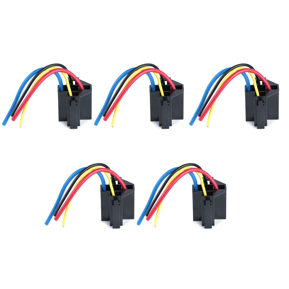
4 pin horn relay wiring. China 4 pin relay wiring diagram horn manufacturers and suppliers factory whole meishuo electric 3 sets 12v 40a spst automotive car 4pin relay and 4 wires harness how to wire a 30 40 relay you rh jd1912 diagram pressure china 4 pin relay switch manufacturers and suppliers factory whole meishuo electric 4 pin relay wiring read more. Mount the new horn and relay in a convenient location under the hood. Nature reliance recommended for you. I need to replace a horn relay which is a usa made omron 4 pin with number 21x7a12 b stamped on the top. Ktm motorcycles with can bus electrical systems 109011901290 series will require that the stock horn be retained and the denali harness be connected in parallel with the original horn wires. High quality heavy duty 40 amp relay 4 pin with fuse and socket harness 30a relay 12v auto relay from china chinas leading automotive power relay product market with strict quality control automotive power relay factories producing high quality heavy duty 40 amp relay 4 pin with fuse and socket harness 30a relay 12v auto relay products.
A 5 pin relay is not included with this kit. 4 pin horn relay wiring 3 pin horn relay wiring diagram horn relay wiring motorcycle bike horn cutout wiring diagram how to install horn in motorcycle dual horn relay wiring diagram motorcycle. Sep 7 2019 this pin was discovered by prwije. Motorcycles with blade style horn wire connections. If using this. The relayfuse box identifies it as 15a.
Relay wiring diagram 5 pin wiring diagram. It shows the components of the circuit as simplified shapes and the capacity and signal connections with the devices. It shows the components of the circuit as simplified shapes and the capability and signal contacts in the company of the devices. The relayfuse box identifies it as 15a. Choose a location close to the battery to reduce the cost of the project by minimizing the amount of heavy gauge wire used. You will notice that on the type b layout pins 86 and 30 are swapped over compared with the type a layout.
Connect a solderless ring terminal to one wire from the inline fuse holder and connect it to the positive terminal. Connect the horn wire to terminal 86 and terminal 85 to terminal 30. Discover and save your own pins on pinterest. 30amp mini fuse for pre connected inline fuse holder. Top five useful knots for camping survival hiking and more duration. Posted by johnno on jul 11 2020.
Wiring diagram for a 4 pin relay wiring diagram is a simplified agreeable pictorial representation of an electrical circuit. A relay is provided with the purchase of a denali soundbomb compact split horn. Finding continuity between the horn wire and the vehicle ground requires wiring the relay differently.


