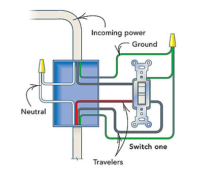
If the switches that control the light show continuity and the lightbulb is known. The two hot wires of three wire cable connect to a pair of brass colored traveler terminals on each switch.
Wiring A Red Series Dimmer Switch With Power From Light For 3
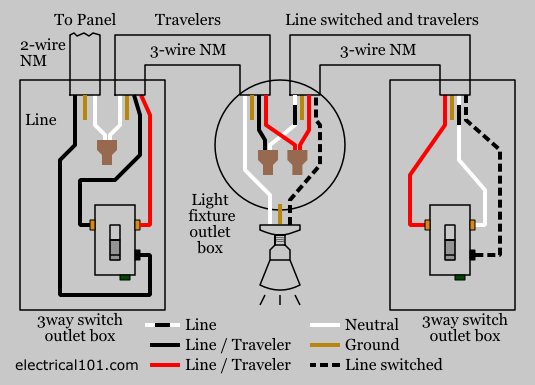
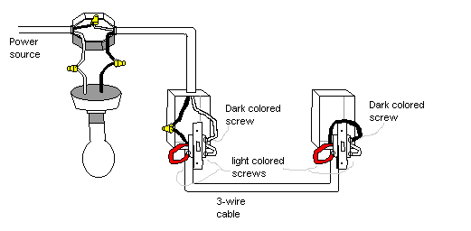
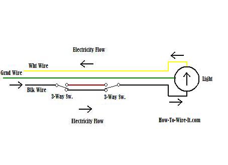
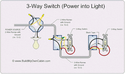
3 way switch power to light. In this diagram the incoming hot wire attaches to the first switchs common dark colored terminal. Three way light switch with power feed via the light. The common screw may be located in a different spot on your 3 way switch than the location indicated in the drawings above but make sure that the wire indicated in the drawings to be connected to the common screw is connected to the common screw of the switch. In the above 3 way switch wiring diagram at each switch the black wire gets connected to the copper or black screw. Since three way switches control the flow of electricity to a light power must flow through the lightbulb socket. Extending the switch leg over to the common as shown in the photo above or extending the hot over to the common as described below.
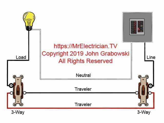
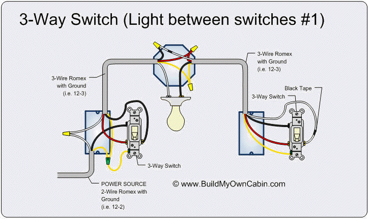
Be sure to mark the white wire as noted so if any future repairs or replacement is needed whoever goes into the box will know it is marked as a hot wire. The black wire from the other 3 way gets connected to the line black wire. This method is commonly used by professional electricians. Power to light to light to switch to switch. The correct wire must be connected to the common screw of a 3 way switch otherwise the switches will not control the light fixtures correctly. This electrical wiring diagram shows power into light switch box 1 wire to light from switch box 1 and from switch box 1 to three way light switch box 2.
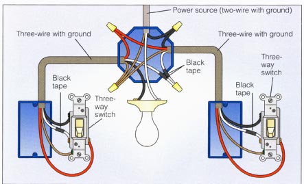
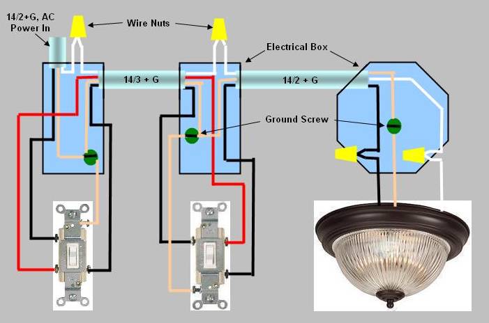
In the ceiling light fixture electrical box one black wire from a 3 way switch gets connected to the black load wire on the light fixture. The hot source is spliced to the white wire which should be marked as being hot with black tap and run through to the common terminal of sw1 and from here the hot from the light is spliced through to the common. Wiring a 3 way switch with the power coming in through the light and flowing to the switches. A dead end 3 way switch wiring method. Note that in this case a larger than normal device box is required at switch 1 location due to box fill calculations most regular size boxes will only accommodate five wires. Wiring diagram for a 3 way switch one of the many wiring diagrams showing different methods of wiring a three way switch circuit.
In this light switch wiring diagram the power feed joins the circuit via the light fixture where a two wire cable c2 runs from the light to the first 3 way switch sw1 and a 3 wire cable c3 joins the two switches. There are 2 variations of dead end 3ways. In this situation you. This 3 way switch wiring diagram shows how to wire the switches and the light when the power is coming to the light switch.
