With this particular guidebook youll be capable to see how every element needs to be linked and also the precise actions you ought to get as a way to effectively full a. In either case applying electrical current to the contacts will change their state.

Pin On Inr Wiring Diagram
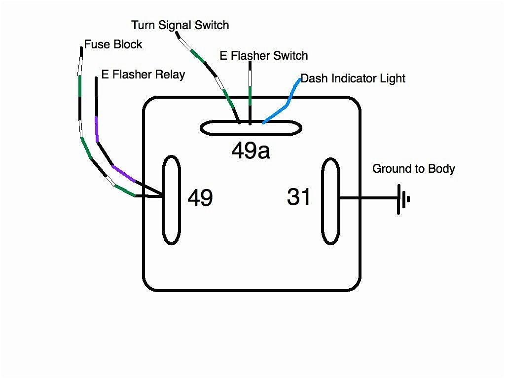
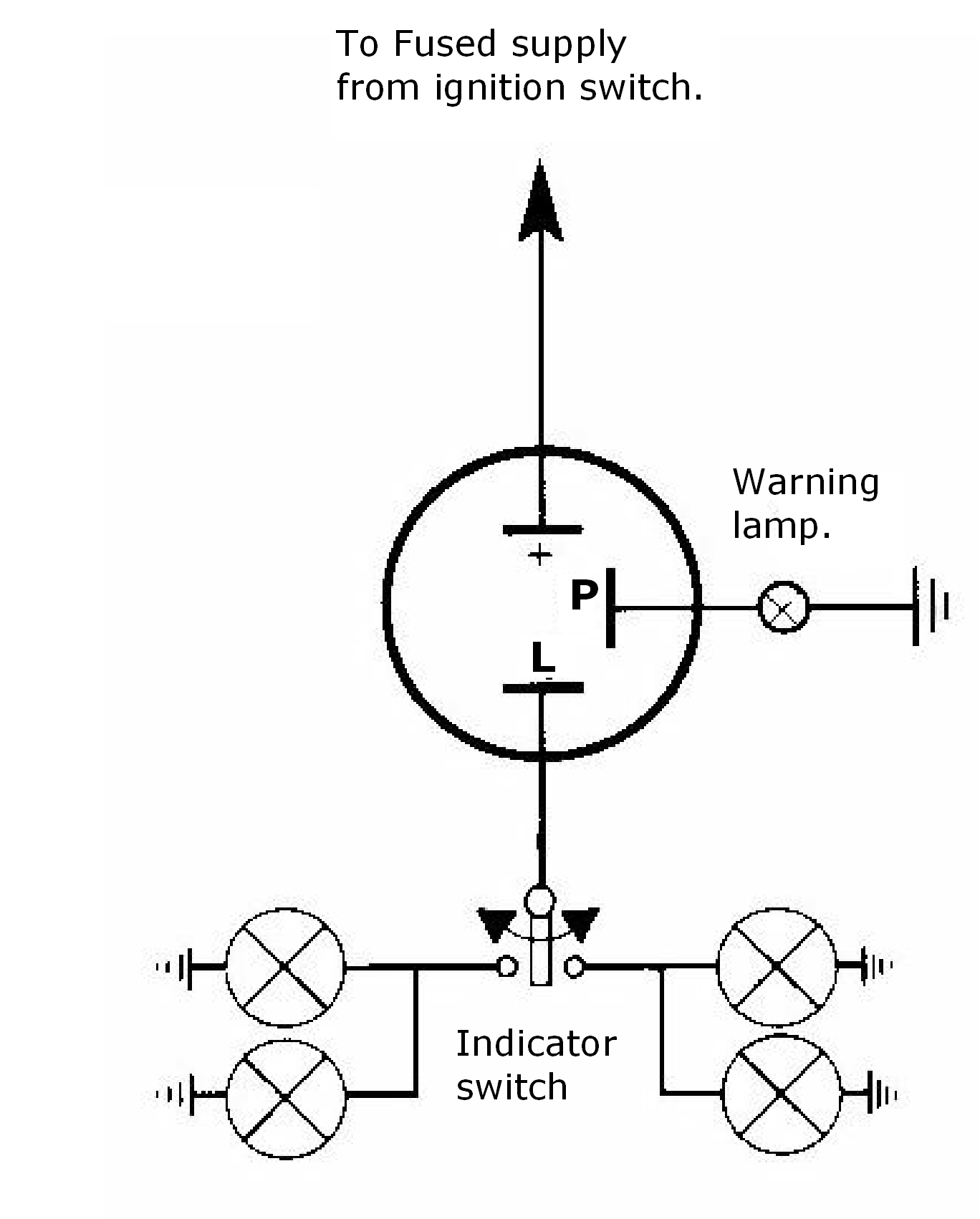
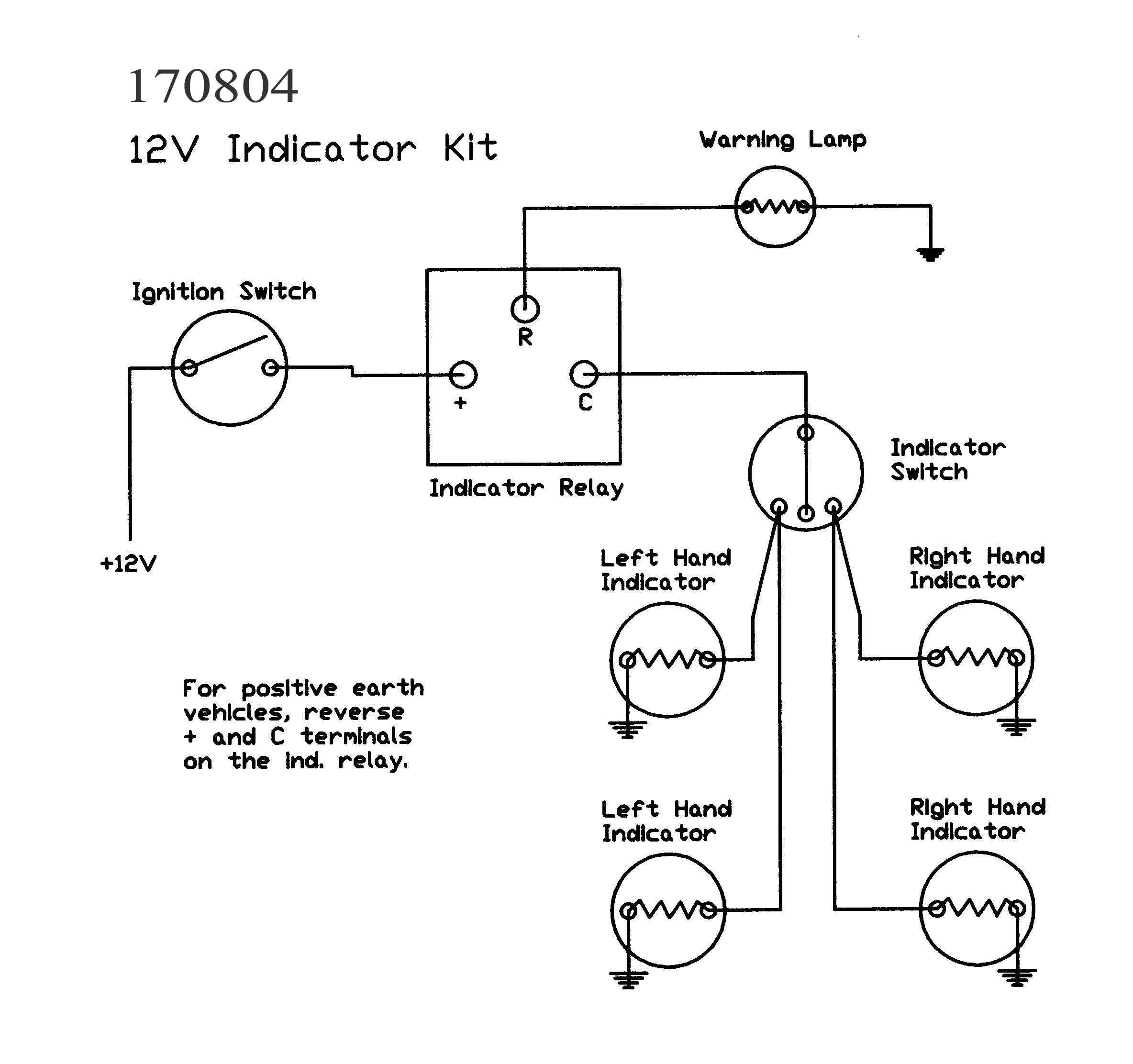
3 pin relay wiring diagram. 8 pin ice cube relay wiring diagram what is a wiring diagram. 12 volt relay wiring diagram. Wiring diagrams for classic car parts from holden vintage pertaining to 3 pin flasher unit wiring diagram image size 600 x 755 px description. A wiring diagram is a simple visual representation with the physical connections and physical layout of your electrical system or circuit. It is meant to help each of the common consumer in building a correct method. If you buy 7x6 inch led headlights or 4x6 headlight and your car socket is not standard h4 to 3 pin adapter is a must.
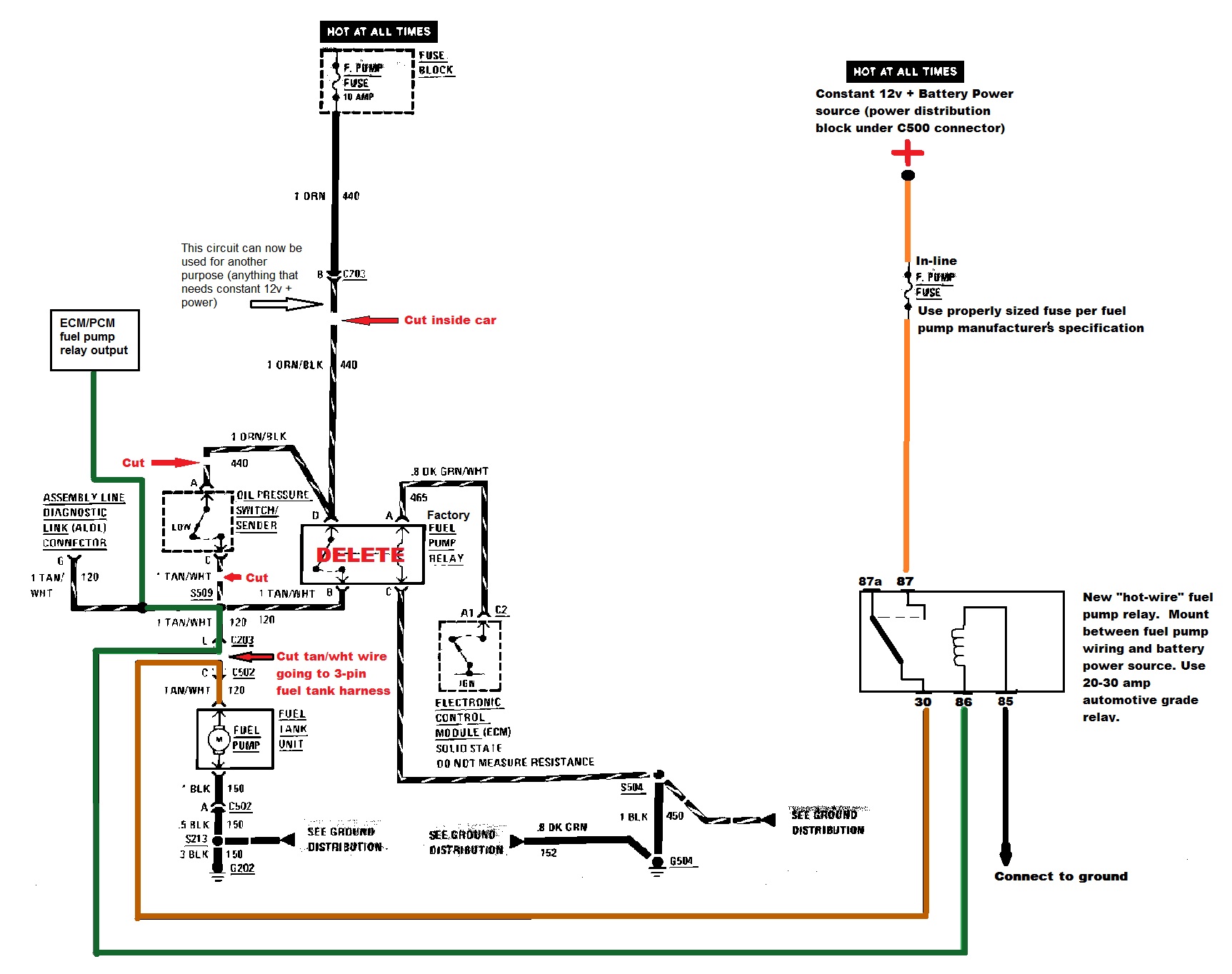
The main power from the battery feeding the fuse and relays should be a nice large gauge wire as indicated. Flasher units norwood parade auto spares open 7 days wwwderekau with 3 pin flasher unit wiring diagram image size 417 x 293 px. Best bosch relay wiring diagram 5 pole electrical outlet symbol 2018. Its fully insulated and contains up to 7. A wiring diagram is a simplified traditional pictorial depiction of an electrical circuit. So use the right size wire.
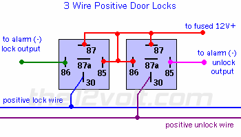
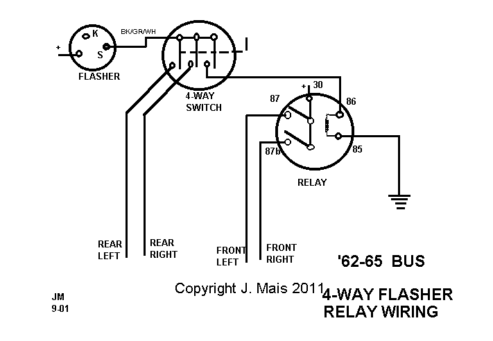
Wiring diagram for a 4 pin relay wiring diagram is a simplified agreeable pictorial representation of an electrical circuitit shows the components of the circuit as simplified shapes and the capacity and signal connections with the devices. Assortment of 12 volt relay wiring diagram. Relays switches are used to open and close circuits electromechanically or electronically. These guidelines will likely be easy to comprehend and implement. When a relay contact is open the relay is not energized. Wiring diagram arrives with numerous easy to follow wiring diagram instructions.
Relays are generally used to switch smaller currents in a control circuit and do not. 3 pin led flasher relay wiring diagram 12v led flasher circuit diagram best 2 pin flasher relay wiring diagram. This caused the headlights not to work properly. Headlight relay wiring diagram the above circuit is a way to use existing headlight wiring to control 2 relays that can be placed close to the lights. September 3 2018 march 13 2019 by larry a. When a relay contact is closed there is a closed contact when the relay is not energized.
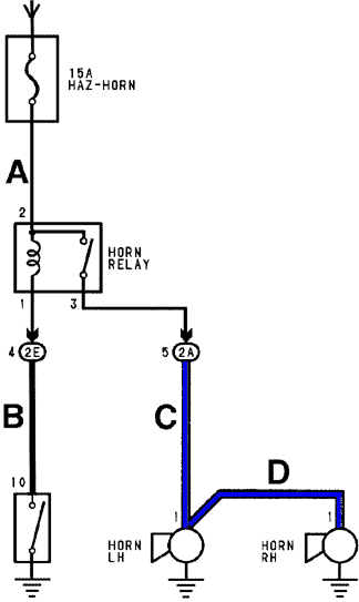
Us spec mk2 fog lamps fog lights only work with dipped beam on 191941595. 12 volt wiring diagram best 12v relay pin 5 and roc grp org in. Needle control valve cyl 2 pin 2 23 mvb1 needle control valve common cyl 123 pin 1 1 toyota tacoma electrical wiring diagram to engine control module4 7 d to bulb check relay comb meter 27 628 4 b w 1 toyota tacoma electrical wiring diagram a 22 3e at 2 mt 2. This video will help you to connect your horn set with 3 pin relay battery and push push button in your car. Ecomatic vacuum pump relay 357959141. Renault clio mk3 headlight relay.
3 pin led flasher relay wiring diagram name. Hvac fan relay wiring diagram download. Free wiring diagram menu. If you like my video then please subscribe to get the latest updates regarding all. 8 pin relay wire diagram wiring schematic wiring diagram 8 pin relay wiring diagram. Here we look at relay switch pin diagram and the different kinds of relay switches.
It reveals the. Early mk3 vr6 mk3 tdi and some mk4 golf diesel relay 357906381a.


