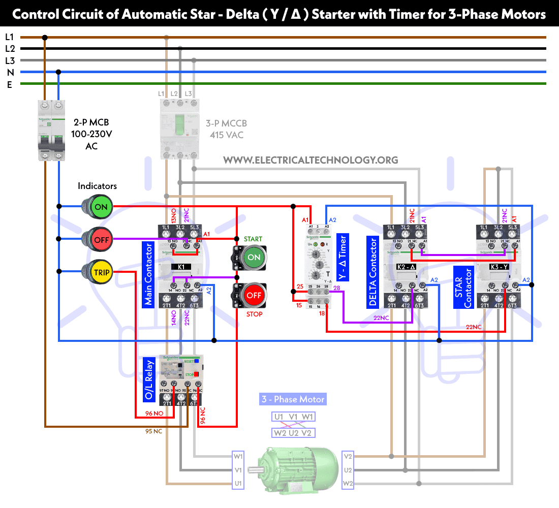
Single phase motor wiring diagram with capacitor baldor single phase motor wiring diagram with capacitor single phase fan motor wiring diagram with capacitor single phase motor connection diagram with capacitor every electrical arrangement is made up of various unique pieces. Wiring diagram book a1 15 b1 b2 16 18 b3 a2 b1 b3 15 supply voltage 16 18 l m h 2 levels b2 l1 f u 1 460 v f u 2 l2 l3 gnd h1 h3 h2 h4 f u 3 x1a f u 4 f u 5 x2a r power on optional x1 x2115 v 230 v h1 h3 h2 h4 optional connection electrostatically shielded transformer f u 6 off on m l1 l2 1 2 stop ol m start 3 start start fiber optic transceiver class 9005 type ft fiber optic push button selector switch limit switch etc.
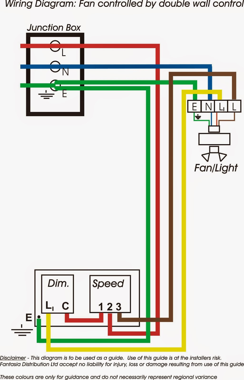
8n Wiring Diagram Diagram Base Website Wiring Diagram
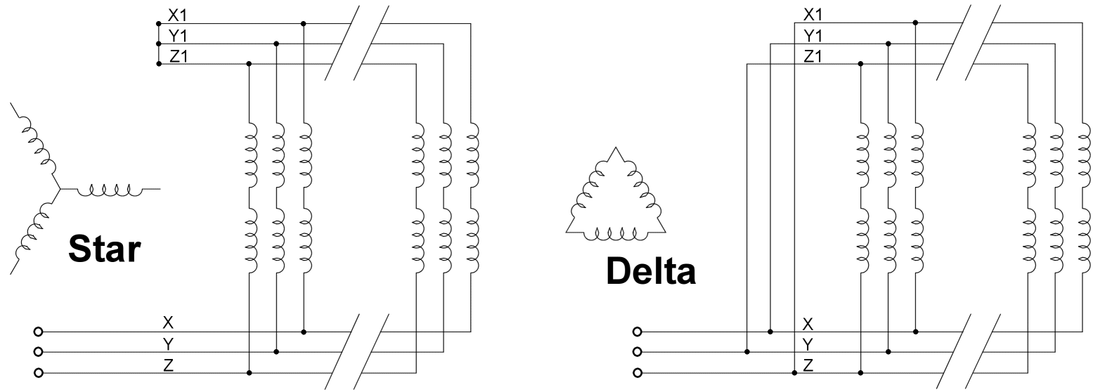
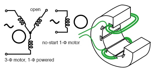
3 phase 2 speed motor wiring diagram pdf. 3 phase or 2 phase 3 wire for 2 phase 3 wire l2 and t2 are common sgl. Power and control circuit for 3 phase two speed motor. Fiber optic cable electrical connections boundary seal to be in. 3ø wiring diagrams 1ø wiring diagrams m 3 m 3 high speed delta connection low speed star connection w2 or white w2 or white u2 or black u2 or black v2 or orange v2 or orange u1 or red u1 or red v1 or yellow v1 or yellow w1 or blue w1 or blue thermal contacts tb white thermal contacts tb white l1 l1 l2 l2 l3 l3 e e codes. The single phase induction motor is much the same in construction as the three phase motor. And upwards diagram dd5 two speed motors for all other single phase wiring diagrams refer to the manufacturers data on the motor.
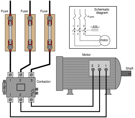
Multi speed 3 phase motor 3 speeds 1 direction power control diagrams one line diagram of simple contactor circuit. One contactor burnt for high speed and a replced contactor does not engange originally the coils re fed with a nutural and the one i replaced is only working with a phase. If not the arrangement wont work as it should be. Phase lines sizes 0l and 1p single phase sizes and 1 direct current 6 pilot light red black sizes 0 1 3 phase with pilot light 8. Like subscribe and dont skip the ads siemens logo tutorials. Some single phase induction motors are also called squirrel cage motors because of the rotors similarity to.
Please help how to go about this. Each component ought to be placed and linked to different parts in particular manner. Refer back to this diagram as the operational requirements of the single phase motor are discussed. Wiring diagram for two speed moto explained. Kindly email me the diagrams for star deltor and direct online for a 3speed 1directon 3ph motor have two of them in a bow cutter. And manufacturers wiring schematics also use diagrams b and c to ensure a positive troubleshoot ing application.
Three phase electrical wiring installation in home iec nec. Multi speed three phase induction motors application general industrial centrifugal machines duty s1 rated voltage 400v frequency 50 hz ambient temperature from 15c to 40c mounting height up to 1000 m above sea level number of free shaft ends 1 insulation class f degree of protection ip 55 different duty type different supply voltage frequency 60 hz number of free shaft ends 2 insulation class h degree of protection ip 56 tropicalization other versions per customers specifications. Figure 17 3 shows a very basic one line diagram of the single phase motor. Capacitor motor single phase wiring diagrams always use wiring diagram supplied on motor nameplate.


