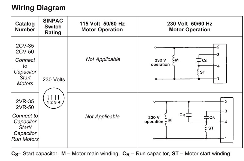
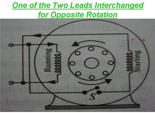
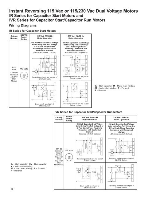
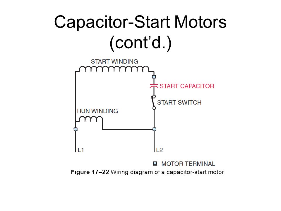
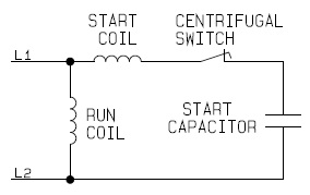
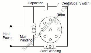
Diagram explanation of how a capacitor is used to start a single phase motor. The reconnection must be carried out by qualified electrician.
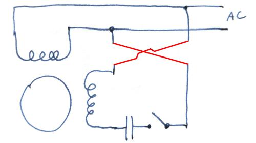
Reversing Single Phase Induction Motors
Wiring diagrams capacitor start motors. Split phase induction split phase permanently connected capacitor split phase capacitor start split phase capacitor run another split phase capacitor run split phase capacitor run induction reversible reactor start split phase single value capacitor dual voltage type repulsion repulsion start induction reversible shaded pole skeleton type shaded pole universal dc shunt motor. It doesnt matter what you need it for youll be able to usually find a list of distinct materials that you will want to perform a job. Not only can you locate various diagrams but you can also get step by step instructions for any specific undertaking or topic that youd like to know more about. Its going to allow you to definitely learn distinct. One often used method is the split phase motors. With the help of the guide youll be able to effortlessly do your own personal wiring tasks.
Types of single phase induction motors electrical a2z single phase induction motors are traditionally used in residential applications such as ceiling fans air conditioners washing machines and refrigerators single phase motor wiring with contactor diagram the plete guide of single phase motor wiring with circuit breaker and contactor diagram. Capacitor start run. Single phase motor wiring diagram with capacitor start. How to connect single phase motor. A list of electric signs and summaries could be found on the electrical icon web page. To read a wiring diagram first you need to know exactly what basic components are included in a wiring diagram and also which pictorial icons are used to represent them.
If not the arrangement wont work as it should be. Single phase motor wiring diagram with capacitor baldor single phase motor wiring diagram with capacitor single phase fan motor wiring diagram with capacitor single phase motor connection diagram with capacitor every electrical arrangement is made up of various unique pieces. Hobbyist diy electronic devices amp. In addition this e book gives practical. Frequent stopstarts andor changing of the direction of rotation will damage the motors capacitors and winding. L1 and l2 are designated as the two connection points representing the two electricity flow path inherent with single phase circuits where a single phase supply voltage is fed to the motors internal circuit.
Another method is the capacitor start induction run motors. Wiring diagrams of small and fractional horsepower electric motors. The single phase induction motor can be made to be self starting in numerous ways. We know about the activity of a. Motor run capacitor wiring diagram wiring diagram explained motor run capacitor wiring diagram. Wiring diagram single phase motors 1empc permanent capacitor motors 1empcc capacitor start capacitor run motors electric motors limited when a change of direction of rotation is required and a change over switch is to be used it will be necessary to reconnect the termination on the terminal block.
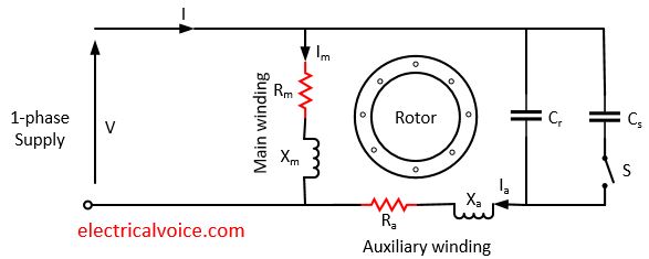
Single phase capacitor start capacitor run motor wiring diagram single phase motor wiring diagram with capacitor. The usual aspects in a wiring diagram are ground power supply cord and link outcome devices switches resistors reasoning entrance lights etc. Capacitor start capacitor run motor the capacitor start capacitor run motor has a cage rotor and its stator has two windings known as main and auxiliary windings. You can often rely on wiring diagram being an important reference that can assist you to preserve time and cash. Electric motor internal wiring diagrams. Wiring diagram not just offers in depth illustrations of whatever you can do but additionally the processes you should stick to although carrying out so.
Single phase motor wiring diagram with capacitor start capacitor run. Each component ought to be placed and linked to different parts in particular manner.

